Soldering

Narwhal

Pre-takeoff checklist
Joined
Aug 6, 2019
Messages
248
Location
Alaska
Display Name
?
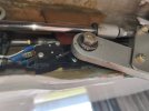
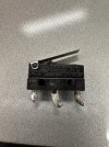
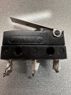
The stabilizer trim in my experimental cub is electric only. It uses these types of limit switches so that when the stabilizer moves up or down to the limit, the spring on this switch compress, opens the circuit, and cuts power to the trim motor.

My problem is that the wiring was not installed with enough strain relief so I need to repair this connection, as I’m getting intermittent stuck trim which can be overcome through bypassing the limit switches or just jiggling the wires that are soldered and heat shrunk to the switch.

I have never soldered anything so can anyone recommend an iron and type of solder suitable for this application? The tabs are very tiny so I think soldering is the only way?
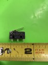
IMG_5510.jpeg
 
Most any soldering equipment could be used for this. I am partial to Weller soldering stations, but even a $10 cheapie could be used. The thing about soldering is you need to have both pieces clean and tarnish free. This switch looks fine, but if you are soldering it to old wires that are tarnished it may be a challenge. Use rosin core solder.
 
Similar limit switches for the gear down lights on a lancair. They all use spade connectors. It may have failed to begin with because it was soldered. That wire bounces around and eventually the solder fails. I would really consider changing to a spade connector.

If you choose to go solder, amazon offers many reasonable options. I recently bought one of these that would work well for your application.

IMG20250601084935.jpg
 
Last edited:
Practice on something first until you get it down; too much wattage or improper technique and you'll melt the lugs out of the plastic. The soldering iron needs to be clean, too. When everything is tinned and ready to go, I like to put a tiny dot of solder on the iron for better thermal conductivity. Then, before it oxidizes, touch it to the part I'm soldering (which will now heat up quickly), flow in a bit of solder, and you're done. Beware cold solder joints; if it looks bad, it is bad. Shiny and smooth is what you want. Alligator clip extra hands help.
 
Reach out to your local amateur radio club. Somebody there homebuilds radios or worked in some sort of electronics. They'll have the right equipment to do it or would be willing to teach you if it is a new skill you'd like to learn. It would take someone with experience about 2 minutes to do what you're asking. If you PM me your location (Alaska is like...really freakin' big) I can try to help you find them.

Otherwise, Forane is on to something. A good quality, tight-fitting spade connector might work better for your application. I usually crimp them and then solder them just to add a little extra security. When properly done, though the crimping is just fine and you probably already have the necessary tools.
 
Lead or Lead free solder, if it is an electrical connection the use of Lead rosin core solder was used for a long time. Now the lead free people want you to use lead free solder, good luck on that. Never use acid core solder on electrical connections.
 
Reach out to your local amateur radio club. Somebody there homebuilds radios or worked in some sort of electronics. They'll have the right equipment to do it or would be willing to teach you if it is a new skill you'd like to learn. It would take someone with experience about 2 minutes to do what you're asking. If you PM me your location (Alaska is like...really freakin' big) I can try to help you find them.

Otherwise, Forane is on to something. A good quality, tight-fitting spade connector might work better for your application. I usually crimp them and then solder them just to add a little extra security. When properly done, though the crimping is just fine and you probably already have the necessary tools.

I'll second this. Putting aside the issue of whether or not soldering is appropriate here, soldering for the first time ever on a flight control is probably not a great idea. Soldering is easy (heck, I've been doing it since pre-teen years, and so did my daughter), but there are some things to look out for that you won't know about. Having someone show you in person (showing what a good solder joint looks like vs a cold one, and some other things) and have you practice a few dozen times on scrap wire is really important.
 
You don't want to solder in a high vibration location. It always fails where the "tinning" ends and the un-tinned wire mass join.
White RTV or a couple layers of heat shrink will provide strain relief.

I have never soldered anything so can anyone recommend an iron and type of solder suitable for this application? The tabs are very tiny so I think soldering is the only way?
Use a low power soldering iron (less than 25W), or find someone that has a temperature-controlled soldering iron.
Loop the wire through the hole in the switch terminal, apply flux and then heat the lug/wire before applying solder. Do your best to find lead solder, avoid lead-free as much as possible. If not sure about what kind of flux you used, clesn it with isopropyl alcohol after you're done soldering. Then (see above) use strain relief for the wires.
 
White RTV or a couple layers of heat shrink will provide strain relief.
RTV should not be used, as it can lead to corrosion. It's also a PITA to remove later. If soldered, the wire should be anchored close to the joint, so there's no motion between the anchor and the solder joint.
 
RTV should not be used, as it can lead to corrosion. It's also a PITA to remove later. If soldered, the wire should be anchored close to the joint, so there's no motion between the anchor and the solder joint.
This. Solder is for the conductivity assurance NOT for any mechanical protection.
 
Lead or Lead free solder, if it is an electrical connection the use of Lead rosin core solder was used for a long time. Now the lead free people want you to use lead free solder, good luck on that. Never use acid core solder on electrical connections.
stay away from lead free in you can. first, its expensive. i pay $23 a pound for 60/40 lead .032 solder. lead free is $90. second, lead free flows like s...t. it takes a bit more skill to use it.
 
Those are solder terminals, but the same switches are available with spade and ring terminals. Google DC2 Cherry Micro Switch.
 
I learned to solder at my first full time job. It was a scale business. The digital age was taking over and our mechanical scales were converted to digital readouts. For some reason we had to change out 16 pin IC chips on display boards. I spent a few months on and off sucking out solder and installing new IC chips in the display boards.

I went on to build pretty many dragsters that were one of the highest vibration machines possible. I soldered many all wire ends on with heat shrink tubing. They held up better than crimped on ends, IMO
 
Most any soldering equipment could be used for this. I am partial to Weller soldering stations, but even a $10 cheapie could be used. The thing about soldering is you need to have both pieces clean and tarnish free. This switch looks fine, but if you are soldering it to old wires that are tarnished it may be a challenge. Use rosin core solder.
To add...if there is enough free wire (service loop anyone?) cut the used wire off, get fresh wire.
 
Soldering is easy. Ask a hangar neighbor or two. One of them will have the tools and will be happy to show you how. In general, you heat the wire so solder flows. No heat? No stick. It isn’t difficult. When finished? Support the wires with tape or zip ties to prevent dangling and movement. If the spades fit crimp fittings and you go that way? Get high quality fittings and a proper crimp tool. Doing crimps poorly is very common.
Doesn’t CC install Safety Trim modules in their Cubs? I wouldn’t want electric trim without one. My G3X has trim limits marked on the screen. The stab can go slightly beyond those limits in both directions. All I have to do is stay between the lines. My trim gets used more than in most Cubs. Safety Trim manages any threat of a stuck switch.
 
Last edited:
The best advice here is to get a HAM radio person to do your solder joint. They will have years of practice and know what to avoid.

They will have the correct tools. I am not a HAM, but for precision soldering on computer cards, I used a somewhat pricy pencil iron with the thermostat built into the very end of the iron. It had interchangeable tips, with not only different shapes and sizes, but different temperature ratings. The individual tips had internal parts that controlled the heater.

For someone using an iron for sensitive work, those irons save money. For the occasional use, they are expensive. The HAM person will also have a selection of heat shrink tubing, and put it on with several lengths and diameters to spread the flex.

For a good chance of anther productive visit, offer some money to cover the "material cost", rather than money for "wages".
 
Has anyone seen their Ford factory radio display dim out over time?
I have a small fleet of Ford work trucks that do that as time goes on. It’s pretty easy to remove the radio and then remove the front of the radio. Resolder the pins and the display goes full brightness again. Easy to do, only have to touch each pin with a tip primed with solder.
 
I've been a HAM for over 50 years. I wouldn't trust most of them to get anywhere near my plane with a soldering iron.
Didn't a HAM invent breadboarding by taking the wife's bread cutting board, driving nails into it and wrapping wires around them?
1749498114801.png
 
stay away from lead free in you can. first, its expensive. i pay $23 a pound for 60/40 lead .032 solder. lead free is $90. second, lead free flows like s...t. it takes a bit more skill to use it.
Depends on the lead free alloy, and a flux that will hold up the higher temperatures. There's a bunch of different lead free alloys. Some have a plastic range like 60/40 and some are eutectic like 63/37. But with almost all your lead free solders, it's going to be a more brittle joint, and require higher temperatures - which sucks for some applications/locations. I would never use lead free on any joint with vibration. 60/40 or 63/37 should hold up just fine, though like someone else said, it ain't supposed to be structural.
 
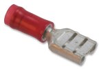
Pre Insulated Diamond Grip (PIDG) terminal properly crimped with ratcheting red/blue crimpers is what I would use. It makes 2 impressions, the second furthest away from from the terminal grabs the insulation and acts as a strain relief. When they model a soldered wire joint, it's mechanically considered a transition from a solid rod to stranded wire that concentrates the stress. I believe it's called a stress rider. A newer crimper will leave a witness mark (impression) that indicates it was properly crimped with the correct tool. Run the wire in a bundle and ensure the bundle is clamped and tied every few inches so the individual wires are no free work loose.
 
Pre Insulated Diamond Grip (PIDG) terminal properly crimped with ratcheting red/blue crimpers is what I would use. It makes 2 impressions, the second furthest away from from the terminal grabs the insulation and acts as a strain relief. When they model a soldered wire joint, it's mechanically considered a transition from a solid rod to stranded wire that concentrates the stress. I believe it's called a stress rider. A newer crimper will leave a witness mark (impression) that indicates it was properly crimped with the correct tool. Run the wire in a bundle and ensure the bundle is clamped and tied every few inches so the individual wires are no free work loose.

That’s all very nice, but the crimped terminal has to fasten to a terminal on the switch designed for that purpose. His switch does not have that. It is a solder terminal.
 
Thanks all. At the bottom here I attached a screenshot of a switch with wires either already soldered in or otherwise integrated into the switch which I am considering. Not sure if it is also waterproof or if they all are but it definitely needs to be. Even if I use the original switch with just the solder tabs I’m going to need to splice in some extra length of wire for more strain relief. I will plan to use a crimp butt splice terminal of some kind for that I guess. That will allow me to solder outside of the airplane and then insert the switch with soldered wires in, then splice the switch in with crimps.

I don’t know of any “safety trim module” in this system, it’s just the switches on the stick, a 2 amp breaker, these microswitches, and the motor mounted to the jackscrew yoke.

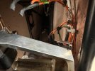
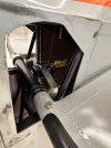
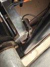
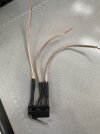
The pictures below are after I’ve removed the problematic switch which is mounted upside down and hits the nose up stop when the forward part of the stabilizer is fully down. The nose down limit switch is still on there. I labeled the loose wires with tape so I can attach them to the new switch correctly. The wires pulled off the switch with two fingers very easily so I think it was just the heat shrink maintaining marginal contact.

IMG_5524.jpeg
IMG_5520.jpegIMG_5517.jpeg
IMG_5526.jpeg
IMG_5525.jpeg
IMG_5515.png
 
Last edited:
So one of your switches attaches to the trim yoke and moves up and down as you trim? I wonder why they did that.
 
So one of your switches attaches to the trim yoke and moves up and down as you trim? I wonder why they did that.

There are two of them on the back left of the trim yoke. One is mounted upside down directly underneath the one on top (that’s the one I removed in the pictures) and it stops power at the nose up trim limit. You can see the one that stops it at the nose down trim limit still attached in the pictures. Everything on the airframe is to keep weight (and cost?) down so I’m sure that’s why.
 
Last edited:
I have a bunch of these in my Velocity. None are soldered. The last thing I want to do is desolder and solder new ones when those microswitches fail.

I used Amp Faston terminals.

View attachment 141775
I use Ancor marine terminals. They have adhesive lined heat shrink that provides a strain relief, and also prevents corrosion.

A calibrated crimper like a Greenlee 45500 is essential for trouble free connections.


ancor-22-18-gauge-5-16-heat-shrink-ring-terminal-100-pack-310599.jpg
 
The pics of the switch with the stub pieces soldered on look pretty terrible to me, but they probably work.

Agree with just about everything above. Soldering little electrical connections isn't difficult. I'd practice on a couple of junk terminals first, similar size and same gauge wire. You'll have it down in a couple of tries. Use 63/37 rosin core solder, not the plumbing size but something like 20 gauge. Too thick is harder to control on a small joint and wicks away heat fast. Thinner is fine, and you can feed it quickly. 60/40 is more common, but 63/37 is better because it's less likely to give you a bad joint if there's any motion while the solder cools. That's the tin/lead ratio. Use the smallest corded electric iron you can find. Have a wet sponge handy.

Simple steps: make sure terminal and wire are clean. No residue of old solder or corrosion. Put the wire through the terminal and fold it back, so it's secure if possible. Ideally, have the switch in a little vice, and the wire secured somehow so it won't move. Movement during the process isn't good. Plug the iron in and wait until it gets hot enough to quickly melt the solder. Wipe the hot tip against the sponge to completely clean it, then touch it with solder to just put a tiny amount on the tip. Touch the tip to one side of the terminal and hold it there. Then start gently tapping the other side of the terminal with the solder until it easily flows. This will probably only take about 2-3 seconds, maybe less. Once it's hot enough to flow the solder, let it flow in, with the flux flowing first, then the solder. That should only take maybe a second. Pull back the solder, then the iron, and let it cool for several seconds until it completely solidifies. That's it. It should be bright and shiny, and should have flowed evenly to the wire and terminal. You want enough solder to fill in the terminal opening, and to be a little convex over that, but not much more.
 
I see a lot about tinning the wire (making the stripped wire rigid by melting a bunch of solder into the strands) before soldering, but if I’m going to bend the wire through the switch’s tab holes before soldering I will need to skip that, right?
 
I see a lot about tinning the wire (making the stripped wire rigid by melting a bunch of solder into the strands) before soldering, but if I’m going to bend the wire through the switch’s tab holes before soldering I will need to skip that, right?
My understanding is that it is not to make it rigid - it is to ensure that the solder already has a good connection to each component already so that the newly-added solder has an easy and 'primed' surface to melt into. However if you'll need to bend the wire that may make it impossible to do so anyway so it may be moot.

Edit - you may want to add rosin beforehand in that case, which removes oxidation from the metal surfaces for best solder bonding.
 
Yeah, I wouldn't tin with those connectors. BP is correct as far as I know on tinning, and it's especially good for large and old wire, because if the solder flows to the wire you're left with a clean layer of solder on it, so it's going to be easy to solder to something else. With small wires less of an issue. Agree on the flux, too, IF the wires are a little corroded. But ideally, the wire and terminal are clean. The flux, when it's hot, removes mild corrosion and wets out the surface so that the solder flows onto it. When things are clean the rosin flux that's inside the solder is perfectly fine. After soldering the rosin flux isn't corrosive, but it's still best practice to clean it off with water or isopro.
 
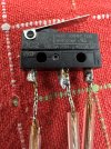
Well I tried it.IMG_5530.jpegIMG_5531.jpeg

It didn’t work. The stabilizer moved but when the limit switch engaged at full nose down travel the trim froze and the breaker popped. I guess I overheated or otherwise damaged the switch when I soldered the wires on.
 
Last edited:
I have a lot of doubt you overheated the switch soldering.

As to your specific solder joints, I usually put a bit more wire into through hole connections so I have more wire wrapped/twisted below the tab.. Hold the soldering iron to the switch tab, and solder on the opposite side of the tab. When that tab is hot enough, the solder will flow and wick into everything.

Is the switch you installed a different switch than you removed?

Do you have a copy of the circuit diagram and an ohmmeter/multimeter that you can use to use?

I don't really think I'd be soldering this either, if I could do crimp terminals, but it sounds like you need to get the circuit figured out as a first priority.
 
:yeahthat: What he said. My guess is that the wires aren't where they need to be on the switch. Maybe you got them in the wrong order on the original switch, or maybe you replaced the switch and the new one isn't the same type (NO vs NC, different pin arrangement). Sounds like when the switch is tripped it's shorting the motor circuit.
 
Back
Top