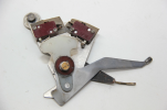
Soldering

Do you really wire your plane up with lamp cord?
 
don't take this the wrong way. im just trying to give you the things ive learned over years and hundreds of thousand solder joints.
1: wrong wire type and wrong size. aircraft wire needs to be tefzel and depending on load, probably 20 gauge max.
2: your stripping is bad. one has cut strands and the insulation is not cut clean and square. believe it or not, the 5 dollar strippers at HF work real well. also too much bare wire left. the insulation should end a lot closer to the switch.
3: if the switch has holes in the tabs, the wire should be looped through the hole and cut clean and close to give a physical lock on the tab.
4: left and center tab had to much heat put on it, you can see the melting of the body of the switch. right tab looks a lot better.
5: a small wire like 20-24 gauge can be tinned and still put through the hole and bent around. tinning it gives faster heat conduction through the wire and better flow without the heat getting to the plastic body.

keep at it, it takes a bit of practice to get consistent good joints. i still get bad ones every now and then.
 
Those lugs are not for soldering. They are for screws and a ring terminal. Who said they should be soldered??
 
Good news is replacement switches are readily available and inexpensive. Buy several so you can practice.

While you are at it, get some mil spec wire and butt splices from Aircraft Spruce, and a pair of ratcheting crimpers from Amazon.
 
You have 2 issues.
1. Your circuit doesn't appear to work. You don't know if the switch is good or bad, which implies you are swapping parts without using diagnostic equipment. I'm repeating myself, but only because it's super important you step backwards and get some diagnostic capability and a wiring diagram before you get too much more time sunk into this.

2. A discussion around aircraft wiring. I don't know where the US equivalent lives, but the Aussies have an Advisory Circular that is useful enough to show up in a lot of places online. You can access the PDF

I would suggest paying attention to
1. Wire selection
2. Wire and cable routing and support
3. Strain relief (which is a lot of #2 above, but also could be heat shrink, which you had smartly used)
4. Termination

Get your circuit working with what you have on hand. Iterate your switch installation and wire installation until you are as close to that AC as you can get yourself. Inspect frequently :)
 
Last edited:
Good point on diagnosis. A 5 dollar voltmeter from HF is sufficient to determine whether the switch has been ruined or just uglified. But IMO when replacement switches are 5 bucks, no harm in preemptively tossing it based on appearance.

Pro tip: before you disassemble or disconnect anything, label all wires and tubes and take a few photos.
 
The new switch was from the aircraft manufacturer, the same type that came off. The wires went on in the same order they came off. I labeled them by position with tape when I removed them. If they were in the wrong order it doesn’t seem likely that the trim would’ve moved at all when the trim switch in the stick was pressed but it did.

I guess I should’ve checked the switch function with a multimeter after soldering but I thought if it was allowing the trim to run, which it did, the switch was probably going to work Ok. As far as the wire I used what I had on hand that was big enough to fit in the 18-22 awg crimp butt splices. I’m clearly not a great electronics technician which makes sense having never done it before so I’m tempted to just take it to a mechanic.
 
Those lugs are not for soldering. They are for screws and a ring terminal. Who said they should be soldered??
Um, no they are indeed solder lugs. If they were for screws they would be tapped. These are classic solder lugs.


Note that it calls out Solder Lug.

What is lacking however is a DC rating. Since this thing is almost certainly switch DC, it's perhaps no wonder why the original failed.
 
Last edited:
Um, no they are indeed solder lugs. If they were for screws they would be tapped. These are classic solder lugs.
I have yet to see soldered switches. Everything I have seen has been screws or crimp.

Soldering is a bad idea. It makes replacement that much harder and soldering as way more issues than mechanical connections.

its E/AB so it really doesn't matter, but I strongly advise against solder. OP doesn't know how to is the biggest red flag.
 
I have yet to see soldered switches. Everything I have seen has been screws or friction.

Soldering is a bad idea. It makes replacement that much harder and soldering as way more issues than mechanical connections.

its E/AB so it really doesn't matter, but I strongly advise against solder. OP doesn't know how to is the biggest red flag.
The only way to use this switch is to solder. If he wants to connect via another way, he needs to use the right switch (frankly, in my opinion he has bigger issues than the soldering here).
 
I agree, his E/AB wiring appears to bet a **** show:

"My problem is that the wiring was not installed with enough strain relief so I need to repair this connection, as I’m getting intermittent stuck trim which can be overcome through bypassing the limit switches or just jiggling the wires that are soldered and heat shrunk to the switch."

Incorrectly installed wiring (has he checked all the wiring for proper routing?)
Intermittent trim operation? lol wut?
Bypassing the limit switch? How is that airworthy? Or even safe?

I think the next condition inspection needs to be done by an AnP that has a clue... one sentence, three safety of flight issues.
 

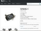
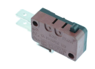
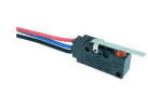
ZF DC2 Series Sealed Subminiature Snap-Action Switches​


ZF Brand: ZF

A wide range of high quality subminiature sealed snap action micro switches from the DC Series, suitable for industries including automotive, white goods, security, vending and office automation.


Dude spend the $15 and get a aviation rated switch. Your life is depending on the same switch that tells you the door to your printer is open.

I'm out, this is completely redonkulus

It’s the switch they used at the factory where the airplane is built. I bought the replacement switch from the factory. The factory installed and designed all of the stabilizer wiring. I didn’t design it. It was a factory builder assist. I’m all for using a different switch if I can find one that has the same mounting dimensions that doesn’t use solder.
 
I "felt" like 43.13's electrical content was condensed (pg 492-609)compared to the Australian AC.
Interesting. Never felt AC 43.13-1B was ever short on required guidance in my experience. However, the advantage that AC 43.13 does have is it can be used as FAA approved data. And if you dig deep enough, you'll find that even CASA will allow the use of the FAA AC 43.13-1B as approved data for certain repairs on VH registered aircraft.

I have yet to see soldered switches. Everything I have seen has been screws or crimp.
Just need to look harder. Unfortunately, there still are a number of areas on legacy aircraft where soldered connections are the preferred method.
 
If you had overheated the switch enough to damage it I'd expect significant damage to the plastic around the terminals, and I don't see it. Your soldering looks better than the close up in post #30 to me. My bet is that it's either something wired wrong, and problem someplace else with the wiring, or the wrong switch.

If you can fly an airplane you can troubleshoot a simple electrical circuit. Just need some patience, ideally a schematic diagram of the thing, and a cheap multimeter. Post the schematic on here and I'm sure someone will help you out.
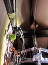
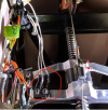
This was my second attempt and it worked. I heated the wire instead of the tabs. I still used too much solder but I wrapped the wire through the tabs, twisted it back around itself, then heat shrinked. Made sure there was no cut strands, so the whiskers on the bottom are from the wire end that has been wrapped back around. Still ugly but it works for now. Used some 20 awg wire instead of the speaker wire; I used the speaker wire on the first one because I thought its floppiness would be good for strain relief, but I got roasted by PoA for that, lol. The mechanic I showed this to said the tinned wires were too long and would probably break eventually due to strain.

I tested the first switch that didn’t work yesterday with a multimeter to diagnose it and it was showing overload between the middle and right tab with the switch pressed down, the second one shows an ohm between those tabs, as did the one I removed from the airplane. It might also somehow have gotten damaged from when I was putting it in the airplane in a very tight space, not necessarily from the heat but I’m not sure. Also could’ve just been faulty.

If it helps those of you concerned about the safety of my solder it’s no big deal to fly this plane with trim stuck full up or down, just annoying. My soldering mastery is second only to my safety wire :biggrin:
IMG_5535.jpeg
IMG_5547.jpeg
IMG_5548.jpeg
 
Last edited:
overload between the middle and right tab with the switch pressed down, the second one shows an ohm between those tabs, as did the one I removed from the airplane

In the picture I quoted - the connector closest to the pivot of the lever is "common" (letter C). With the lever up, the middle terminal (NO - normally open) should show an "open" (no connection) with the common and the pin away from the pivot (NC normally closed) should show only an ohm or three. With the lever pressed, the common and middle should be connected (few ohms) and the NC pin should show open. There should never be a connection (a few ohms) between NO and NC.

Note: The above assumes that the switch is not connected to the rest of the circuit. Checking resistance (ohms) with the part in the circuit can give you stupid readings because you are reading the resistance of whatever is connected as well. Checking resistance with the switch in the circuit and the power on is a no-no.

To check things out with the power on, you test on the "volt" scale and check between pins and ground and what you see depends both on the switch position and if you have the trim button pressed...

A wire diagram would answer a LOT of questions.
 
If you had overheated the switch enough to damage it I'd expect significant damage to the plastic around the terminals, and I don't see it. Your soldering looks better than the close up in post #30 to me. My bet is that it's either something wired wrong, and problem someplace else with the wiring, or the wrong switch.
The solder lugs are connected direct to the inside of the switch. You can easily damage the switch without melting the external case. Not saying that's what happened and you are right it would take seconds to verify this had happened.
 
Great work, congrats!

I would probably put a tiny zip tie or two on that white bundle, so the wires can lend some mutual support.
 
Great work, congrats!

I would probably put a tiny zip tie or two on that white bundle, so the wires can lend some mutual support.
That, or go for the high end cable porn look and put the wires in braided nylon sleeve and heatshrink the ends.
 
Just looking at the last few photos that's not an aircraft grade of wire. Aircraft wire is coated with tin, silver or nickel depending on the temp rating unless with very few exceptions.
 
Just looking at the last few photos that's not an aircraft grade of wire. Aircraft wire is coated with tin, silver or nickel depending on the temp rating unless with very few exceptions.
Depends on how old your plane was. Mine was full of cloth and rubber coated wiring, much of which dated back to 1950 when it was built (or older, we found a rubber hose with a date stamp of 1947).
 
Great work, congrats!

I would probably put a tiny zip tie or two on that white bundle, so the wires can lend some mutual support.
Those wires are going to break again. Look at the picture:

1749832176442.png

That shiny aluminum yoke runs back and forth on the jackscrew. Every time it moves, those wires flex from nearly straight to doubled up. That puts bending forces on the soldered connections and the wire near them, and they will break. Looks also like there's almost enough wire there to get between the cable and pulley when the yoke gets near full aft and the wire doubles up. That could create control problems and wire chafing and shorting. The sharp edges of that yoke will also chafe them.

Those wires need to be anchored securely to some rigid point near the switch to prevent repeated bending at the connections, like maybe the inboard screw on the other microswitch, or even over to the bolt and nut connecting the cable to the yoke. They should also be longer and run more vertically to some point midway along the travel to keep them out of trouble. Might also need more flexible wire if extra length can't be used.
Just looking at the last few photos that's not an aircraft grade of wire. Aircraft wire is coated with tin, silver or nickel depending on the temp rating unless with very few exceptions.
Sure looks like Tefzel to me. He got them too hot and blackened the tinning.

1749832759189.png

I see a "59" there. If he used 20 gauge, that makes it M22759/16-20-9 wire. 18 gauge would be M22759/16-18-9. The "9" means the insulation is white.
https://www.aircraftspruce.com/catalog/elpages/unshieldlwire.php
 
Those wires need to be anchored securely to some rigid point near the switch to prevent repeated bending at the connections, like maybe the inboard screw on the other microswitch, or even over to the bolt and nut connecting the cable to the yoke.

How about right to the yoke where the wires cross it?

Def need to check wiring at both limits of yoke ROM.
 
It’s the switch they used at the factory where the airplane is built. I bought the replacement switch from the factory. The factory installed and designed all of the stabilizer wiring. I didn’t design it. It was a factory builder assist. I’m all for using a different switch if I can find one that has the same mounting dimensions that doesn’t use solder.
Its an EXPERIMENTAL... they can use a rubber band and a bobby pin if they wanted to. 'Factory' means nothing in the E/AB world. Of all the things to cheap out on... something that directly affects a primary control surface. YIKES DUDE.

I'm not trying to berate you, but you don't seem to grasp the situation. Get a EAA tech inspector or a GOOD AnP to look over that plane... you may not see a lot of the problems due to lack of experience.
 
Last edited:
It would be better if the switches were on the same surface or bulkhead as the stop. They then wouldn't need to stress the wires every time it moved.
 
It would be better if the switches were on the same surface or bulkhead as the stop. They then wouldn't need to stress the wires every time it moved.
Yes, that's how most OEMs do it. The switches don't move. Only the yoke or nut or tube or whatever. The wired stay put.
 
Its an EXPERIMENTAL... they can use a rubber band and a bobby pin if they wanted to. 'Factory' means nothing in the E/AB world. Of all the things to cheap out on... something that directly affects a primary control surface. YIKES DUDE.

I'm not trying to berate you, but you don't seem to grasp the situation. Get a EAA tech inspector or a GOOD AnP to look over that plane... you may not see a lot of the problems due to lack of experience.
Overreaction, dude. The microswitches that even Cessna sells are just good-quality industrial microswitches. These aren't airliners where stuff is expected to last for 50,000 hours, and where a stuck trim could overpower the pilots.

A flap microswitch direct from Textron/Cessna:

1749848474505.png

A close-up of that switch:

1749848524399.png

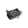
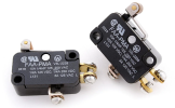
It's a V3L-3 switch. Look at the voltage/amperage ratings on it. 15.1 amps at 125 VAC or 250 VAC. Since when do Cessnas have 125 or 250-volt systems in them? And like any switch, the voltage ratings for DC are much lower.

Now look at this industrial switch:

1749849457252.png

And a close-up:

1749849711786.png

Well, look at that. It's a V3L switch, too. And despite being from an industrial supplier, it's FAA-PMA approved, while the one from Textron/Cessna is not. Go figure. But it's also a quarter of the Cessna switch, which is still too much money.

Now, these are GOOD switches. The OP has a Cherry microswitch with the same ratings on it. Might be made in China. But it's a recognizable name, unlike much that is sold on Amazon and so forth. About $10 instead of the $100+ for the Mouser Electronics switch, or as much as $500 for the Cessna switch that comes with certification paperwork. I have microswitches here that I bought for less than $2 each. Homebuilding is partly about building an airplane to save money, right? So what if the Cherry is only good for 100,000 actions rather than a Honeywell's million-plus actions? If the trim stops are reached once each flight (which they should not be; there is no good reason to run the trim to the stop unless the CG is way off), then that switch is good for 100,000 hours. It will corrode internally long before that. The OP's switch didn't fail due to being worn out; it failed because a wire broke off.

 
Overreaction, dude. The microswitches that even Cessna sells are just good-quality industrial microswitches. These aren't airliners where stuff is expected to last for 50,000 hours, and where a stuck trim could overpower the pilots.

A flap microswitch direct from Textron/Cessna:

View attachment 141936

A close-up of that switch:

View attachment 141937

It's a V3L-3 switch. Look at the voltage/amperage ratings on it. 15.1 amps at 125 VAC or 250 VAC. Since when do Cessnas have 125 or 250-volt systems in them? And like any switch, the voltage ratings for DC are much lower.

Now look at this industrial switch:

View attachment 141941

And a close-up:

View attachment 141943

Well, look at that. It's a V3L switch, too. And despite being from an industrial supplier, it's FAA-PMA approved, while the one from Textron/Cessna is not. Go figure. But it's also a quarter of the Cessna switch, which is still too much money.

Now, these are GOOD switches. The OP has a Cherry microswitch with the same ratings on it. Might be made in China. But it's a recognizable name, unlike much that is sold on Amazon and so forth. About $10 instead of the $100+ for the Mouser Electronics switch, or as much as $500 for the Cessna switch that comes with certification paperwork. I have microswitches here that I bought for less than $2 each. Homebuilding is partly about building an airplane to save money, right? So what if the Cherry is only good for 100,000 actions rather than a Honeywell's million-plus actions? If the trim stops are reached once each flight (which they should not be; there is no good reason to run the trim to the stop unless the CG is way off), then that switch is good for 100,000 hours. It will corrode internally long before that. The OP's switch didn't fail due to being worn out; it failed because a wire broke off.

The TC holder has wide latitude to select components and materials. The owner of American Champion likes to joke he could install a Walmart toaster legally.
 
Note that unlike the OP's switch, this one is rated for DC use.
 
Overreaction, dude. The microswitches that even Cessna sells are just good-quality industrial microswitches. These aren't airliners where stuff is expected to last for 50,000 hours, and where a stuck trim could overpower the pilots.

A flap microswitch direct from Textron/Cessna:

View attachment 141936

A close-up of that switch:

View attachment 141937

It's a V3L-3 switch. Look at the voltage/amperage ratings on it. 15.1 amps at 125 VAC or 250 VAC. Since when do Cessnas have 125 or 250-volt systems in them? And like any switch, the voltage ratings for DC are much lower.

Now look at this industrial switch:

View attachment 141941

And a close-up:

View attachment 141943

Well, look at that. It's a V3L switch, too. And despite being from an industrial supplier, it's FAA-PMA approved, while the one from Textron/Cessna is not. Go figure. But it's also a quarter of the Cessna switch, which is still too much money.

Now, these are GOOD switches. The OP has a Cherry microswitch with the same ratings on it. Might be made in China. But it's a recognizable name, unlike much that is sold on Amazon and so forth. About $10 instead of the $100+ for the Mouser Electronics switch, or as much as $500 for the Cessna switch that comes with certification paperwork. I have microswitches here that I bought for less than $2 each. Homebuilding is partly about building an airplane to save money, right? So what if the Cherry is only good for 100,000 actions rather than a Honeywell's million-plus actions? If the trim stops are reached once each flight (which they should not be; there is no good reason to run the trim to the stop unless the CG is way off), then that switch is good for 100,000 hours. It will corrode internally long before that. The OP's switch didn't fail due to being worn out; it failed because a wire broke off.
DUDE you cannot see the differences? All connections are mechanical and come with proper hardware. The rocker arm has a roller bearing is an not cantilever to reduce stress and a thicker. The 'top' plate is not connected to the mounting holes so if you torque the mounting bolts you don't affect the internal components. I bet if you cut both open you'd see even more differences.

If you think this is 'comparable' to the $2 'factory' switch OP is using then you are wearing some thick rose colored glasses.

Is it crappy analogy time yet? Cause I got like 50 of em ready to go.

"The OP's switch didn't fail due to being worn out; it failed because a wire broke off."

I am to understand that OP didn't build this AC? So everything on it cannot be attributed to his decision making. But now we can see that there are, in fact, several issues that *should* be corrected. Now if OP wants to fly with what he's got then great... have at it. But to argue that whats on there now is 'working' (its clearly not as he's had to wiggle and jiggle a SAFETY SWITCH!!!!!!!!) is a good discussion to have.

Its hilarious, and freighting, that some people would argue this point... the switch is mounted improperly, the wiring is improper and who knows what else.... and this is an fairly easy fix... maybe $50 for some proper connectors, a proper switch, and properly run wiring.
 
Last edited:
DUDE you cannot see the differences? All connections are mechanical and come with proper hardware. The rocker arm has a roller bearing is an not cantilever to reduce stress and a thicker. The 'top' plate is not connected to the mounting holes so if you torque the mounting bolts you don't affect the internal components. I bet if you cut both open you'd see even more differences.

If you think this is 'comparable' to the $2 'factory' switch OP is using then you are wearing some thick rose colored glasses.

Is it crappy analogy time yet? Cause I got like 50 of em ready to go.

"The OP's switch didn't fail due to being worn out; it failed because a wire broke off."

I am to understand that OP didn't build this AC? So everything on it cannot be attributed to his decision making. But now we can see that there are, in fact, several issues that *should* be corrected. Now if OP wants to fly with what he's got then great... have at it. But to argue that whats on there now is 'working' (its clearly not as he's had to wiggle and jiggle a SAFETY SWITCH!!!!!!!!) is a good discussion to have.

Its hilarious, and freighting, that some people would argue this point... the switch is mounted improperly, the wiring is improper and who knows what else.... and this is an fairly easy fix... maybe $50 for some proper connectors, a proper switch, and properly run wiring.
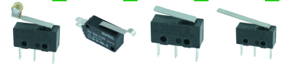
I was pointing out that Cessna sells an industrial microswitch for flap limit functions. They do not build or buy some special aviation switch. The lever design is irrelevant. The OP's lever just makes it a different part number, not a "cheap" microswitch.

1749861109930.png
Some have no lever at all.
1749861191210.png

Then there are various terminals. Screw, solder, spade. Solder connectors are found in certain aircraft like the Continental injected engines in the 185, 206, 210 and others. The switches are tiny and control the fuel boost pump that the pilot switches on if the engine pump fails. The switch is cam-actuated off the throttle lever on the servo on the engine and switches a resistor in and out of the circuit. Soldered connection, in a certified airplane.

Some come with the wires already permanently installed.
1749861255668.png

There are microswitches that are housed in strong, sealed containers.
1749861386018.png
1749861483045.png

Cessna uses industrial switches in the flap actuator control of the airplanes built after about 1978.


1749861871128.png
 
The TC holder has wide latitude to select components and materials. The owner of American Champion likes to joke he could install a Walmart toaster legally.
In our Citabrias, the cowling fasteners between the top and bottom cowls were aircraft screws running into cheap industrial clip nuts. Those nuts were so soft that you had to be really careful not to start them cross-threaded or it was all over. I made a minor mod to both airplanes to install all-metal aircraft anchor nuts on aluminum strips that were riveted to the bottom cowl.

Many airplanes used automotive stuff like door handles, and window cranks as trim cranks.
 
In our Citabrias, the cowling fasteners between the top and bottom cowls were aircraft screws running into cheap industrial clip nuts. Those nuts were so soft that you had to be really careful not to start them cross-threaded or it was all over. I made a minor mod to both airplanes to install all-metal aircraft anchor nuts on aluminum strips that were riveted to the bottom cowl.

Yup, I made the same mod to my Decathlon. Those clip nuts are a mess. I still have them on the belly pan.
 
The solder lugs are connected direct to the inside of the switch. You can easily damage the switch without melting the external case. Not saying that's what happened and you are right it would take seconds to verify this had happened.
You're correct, of course, that they go to the inside. I'm basing my observation/guess on the typical switch design having the lugs held in place by the plastic case itself, so that if the lug is overheated much it'll deform the case...and my own experience from ages ago wiring up small switches and devices before I had a temp controlled iron.

Anyway, glad OP got this straightened out.
 
Back
Top