NA Adding an outlet to a bathroom

Must be nice to live in a house with the breaker indoors! Our panel is outside. On the side of the house furthest from any door. Maybe 100 feet down a side deck from which I don't bother to shovel the snow in the winter. In a location furthest from the garage, in which I've set up my woodshop. The woodshop with the stationary tools that trip breakers with some regularity. I'm looking at you, bandsaw...
I had a detached garage that, until I had the electrical service upgraded, ran off a 20-amp fuse in the house.

I could run the lights, window air conditioner, table saw, and dust collector and never blew the fuse. I did have to start them in the right order, however, or the lights would dim and not brighten back up.

I probably should’ve checked for a penny under the fuse…wouldn’t surprise me with some of the electrical stuff the previous owner did.
 
I just wired the whole house in 8ga wiring, [...] and went straight to the hots in the panel.
No joke. Rented a house where someone had tied in directly to the drop from the meter (before the main disconnect) and ran the wires across a drop ceiling over to a bench where (I suspect) he/she/it had some amateur radio stuff.
 
Just use a 10mm socket as your breaker/fuse. Where do you think they all end up?
 
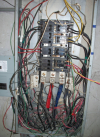
Actual panel from the Haitian hospital we were renovating:

1746035727117.png

Yes, that is indeed lamp cord spliced with electrical tape. I was amazed the place could have the lights on without also being on fire.
 
Actual panel from the Haitian hospital we were renovating:

Yes, that is indeed lamp cord spliced with electrical tape. I was amazed the place could have the lights on without also being on fire.
When I redid the garage/workshop wiring, I there was 1 run that had 4 different types of wire spliced with electrical/duct tape. No junction box, just a tape splice. Romex with and without ground, cloth two wire, underground flat wire. Where there wasn't a ground wire to carry through he just left it hanging out of the splice. I didn't save ANY of the wiring in the shop. Yanked all of it out and started with new Romex.
 
Who can trust that?? As we've established, GFCI's protect the downstream loads, but this illustration clearly shows the loads "upstream":
View attachment 140534
Sheesh... :rolleyes:

:biggrin:
I’ll stipulate you know more about this than I do. But to clarify, can you explain? It looks to me like upstream is coming in from the upper right, making the second outlet downstream of the GFCI receptacle. Or am I using those terms wrong?
 
When I redid the garage/workshop wiring, I there was 1 run that had 4 different types of wire spliced with electrical/duct tape. No junction box, just a tape splice. Romex with and without ground, cloth two wire, underground flat wire. Where there wasn't a ground wire to carry through he just left it hanging out of the splice. I didn't save ANY of the wiring in the shop. Yanked all of it out and started with new Romex.

I'm just finishing up another mission project, this one to Northern Cyprus (the portion under Turkish occupation). While doing the site inspection, I found one breaker with six wires stuffed into it. Only one wire was still being used; the other five had gone to water pumps and some kitchen equipment that were no longer there, and someone had simply snipped the wire off at the load. The breaker had been sized to handle to total load, not the wire size, so it didn't protect any of the wires at all.

I swear, some electrical DIYers are wannabe arsonists.....
 
I’ll stipulate you know more about this than I do. But to clarify, can you explain? It looks to me like upstream is coming in from the upper right, making the second outlet downstream of the GFCI receptacle. Or am I using those terms wrong?

You're correct Eddie, but the diagram may confuse some because everyone knows that, in the northern hemisphere, electricity flows from left to right.
:biggrin:
 
Bath toast sounds better than Toilet Waffles. Mine always turn out shi*ty.
 
You're correct Eddie, but the diagram may confuse some because everyone knows that, in the northern hemisphere, electricity flows from left to right.
:biggrin:
It does, then R->L, then L->R, then R->L, then L->R, then R->L, then L->R, then R->L, then L->R...
 
A bit off topic, but along the lines of wiring nightmares...

Chalet Suzanne resort in FL was a wonderful fly-in destination. We visited it right before it closed. The lack of maintenance was pretty glaring towards the end.

16028273669_82d577fcab.jpg
 
I’ll stipulate you know more about this than I do. But to clarify, can you explain? It looks to me like upstream is coming in from the upper right, making the second outlet downstream of the GFCI receptacle. Or am I using those terms wrong?
I'm being absolutely silly, and making a dumb joke about "up" and "down" which have nothing to do with "upstream" and "downstream". Please do not follow my advice for wiring GFCI outlets.
 
Which isn't guaranteed to work. The only LEGITIMATE way to test is to push the test button on the GFCI itself and verify that the receptacle you are concerned with goes offline.

Note that there are restrictions on WHERE in the bathroom you can place receptacles. If you're putting one in for a power bidet, make sure you put it on the far side of the toilet from the tub/shower if one is nearby, for example.
That depends on the state. In some places you can put an outlet right next to the tub as long as it's GFCI'd.
 
Which isn't guaranteed to work. The only LEGITIMATE way to test is to push the test button on the GFCI itself and verify that the receptacle you are concerned with goes offline.
What is the failure mode where this device won't work? And how does passing the test button on the GFCI confirm that the GFCI will properly activate on downstream receptacles?
 
Remember, the GFCI will cut the power in about the time it takes to say "SH". By the time you get to "IT" the power is already off.
 
Which isn't guaranteed to work. The only LEGITIMATE way to test is to push the test button on the GFCI itself and verify that the receptacle you are concerned with goes offline.
Unfortunately it doesn’t always provide a valid test.
 
No joke. Rented a house where someone had tied in directly to the drop from the meter (before the main disconnect) and ran the wires across a drop ceiling over to a bench where (I suspect) he/she/it had some amateur radio stuff.
If he's going to go that far, might as tie in BEFORE the meter, right?
 
Which isn't guaranteed to work.

Really? I've been using them for decades, never had one fail yet. Mine have either a CE or an ETL certification, so they've been through 3rd-party testing and thus have pretty good assurance of design and build quality. Have you had problems?


The only LEGITIMATE way to test is to push the test button on the GFCI itself and verify that the receptacle you are concerned with goes offline.

That's a necessary but insufficient test, as it only simulates a fault at the GFCI receptacle, not a downline fault.
 
That's a necessary but insufficient test, as it only simulates a fault at the GFCI receptacle, not a downline fault.
I had two that tested fine with the test button, but wouldn’t trip for an actual fault in the outlet. Took a while to figure that out.
 
Really? I've been using them for decades, never had one fail yet. Mine have either a CE or an ETL certification, so they've been through 3rd-party testing and thus have pretty good assurance of design and build quality. Have you had problems?


That's a necessary but insufficient test, as it only simulates a fault at the GFCI receptacle, not a downline fault.
Sorry, but the above is unequivocalby incorrect.

If the tester trips the GFCI, you are fine. But there are times the tester won't trip the GFCI when it should (notably booted or absent grounds) The button is the only LISTED way to test no matter what markings some manufacturer put on the testor.

Using the button IS A SUFFICIENT TEST. This is the way the GFCI passed its listing. The TEST button works the same for the pins on the receptales as it does for the load terminals. Just what do you think your tester is doing differently? It's doing a less reliable induction of a ground fault.
You contradicted yourself, and you didn't list any conditions where the external tester would not accurately work.

There may be problems between the GFCI and the downstream outlets that prevent the GFCI from functioning, even though the GFCI passes the internal test. Therefore that internal button IS NOT A SUFFICIENT TEST. The external tester is MORE reliable and tests for more potential issues.
 
Just what do you think your tester is doing differently? It's doing a less reliable induction of a ground fault.

The tester isn't doing anything differently; it's doing the same thing at a different location.

But there are times the tester won't trip the GFCI when it should (notably booted or absent grounds)

EXACTLY! That's the point! Using the GFCI button is not an assurance that the downstream receptacles are protected, because there could be a fault that precludes it being tripped. That's why testing with the GFCI button only is insufficient.

The tester works by shunting a small current into the ground wire, so that there is a difference between currents on the hot and neutral wires which then trips the GFCI. If there is a break in the ground wire between the GFCI and the downstream receptacle, or if the ground wire is not connected at the downstream receptacle, no current can be shunted and the GFCI won't trip using the tester, but it will still trip using the test button built into the GFCI.

Using the button IS A SUFFICIENT TEST. This is the way the GFCI passed its listing.

The button is a sufficient test of the GFCI itself, but NOT of the entire circuit it's trying to protect. So you use the button at the GFCI, then use the tester at the downstream receptacles.
 
Our current house, the GFCI is a breaker in the panel protecting the entire circuit. Sounds convenient, until it trips and you have to go down two flights of stairs to the basement to reset it, then back up two flights of stairs to the bathroom again.
Dressed only in a towel…
 
You can argue that all you want but it is wrong. The code REQUIRES you to follow the manufacturer's instructions and I have never see a manufacturer recommend one of these hack testers.

I don't know what "failure" you think is going to happen. If you had a clue how these things worked, you'd know you're being silly. The load screws are connected directly to the same internal metal as the receptacle holes themselves. There's no way for it not to work the same way in both places.

You yourself stated in post #67 how a missing ground downstream could prevent the GFCI from tripping on a downstream fault.

Manufacturers’ instructions only relate to the device itself. And I most certainly “have a clue” about how GFCIs work.

Argue all you like, Ron, but your own statements argue against you.
 
As I am learning from our new home construction, codes don't allow for an outlet within 6 feet of the tub. Apparently that is the normal length of the cord of a hair dryer or toaster.

The things you learn...
Yet every outlet in a bathroom has to be GFI, and every hairdryer made within the last 10+ years or so also has to have a GFI. Some NEC rules are just stupid. Outlet spacing in particular. Requiring floor outlets to maintain 6' distances when outlets can't be put in walls is one of the worst.
The tester isn't doing anything differently; it's doing the same thing at a different location.


EXACTLY! That's the point! Using the GFCI button is not an assurance that the downstream receptacles are protected, because there could be a fault that precludes it being tripped. That's why testing with the GFCI button only is insufficient.

The tester works by shunting a small current into the ground wire, so that there is a difference between currents on the hot and neutral wires which then trips the GFCI. If there is a break in the ground wire between the GFCI and the downstream receptacle, or if the ground wire is not connected at the downstream receptacle, no current can be shunted and the GFCI won't trip using the tester, but it will still trip using the test button built into the GFCI.


The button is a sufficient test of the GFCI itself, but NOT of the entire circuit it's trying to protect. So you use the button at the GFCI, then use the tester at the downstream receptacles.
Yeah...the little tester is testing both the gfci and the ground. But that's a problem, not a feature. The outlet is completely safe with a GFCI with or without that ground. And I believe a non-grounded outlet can be replaced by a GFCI, legally, without a ground, as long at is marked 'no ground'.

I say this because most of the time for consumer gear, the equipment ground isn't part of the safety features anyway, because things like razors and hair dryers don't even have a connection to ground, nor do they need one. The ground is generally for big metal stuff where the metal is exposed, so it needs to be grounded.

But the thing to remember is that any GFCI isn't perfect protection even if it is perfect in it's function, because NONE of them will prevent a hot to neutral shock. They just prevent you from having the shock that occurs when you're connected to ground, through that bathtub for example, and a hot.
 
Yeah...the little tester is testing both the gfci and the ground. But that's a problem, not a feature.

Well, I disagree with that. I certainly want to find out if the ground is missing. The little tester will show the missing ground and not trip the GFCI when the circuit might be "safe" (see below), but it can't yield a false indication of a safe circuit when it isn't. Therefore I see it as a feature, not a problem.

The outlet is completely safe with a GFCI with or without that ground.

Safety is relative. It's true that the GFCI will trip if the ground wire is missing and a person provides the ground path, but it's better and safer for the GFCI to trip as soon as a defective piece of equipment is plugged in or the fault occurs, rather than letting a person come in contact with an energized surface at all. That's why all new construction requires grounded receptacles, even on GFCI circuits. Use of a GFCI in lieu of a ground wire is only permitted for older construction when replacing legacy ungrounded receptacles. (NEC 406.4)


But the thing to remember is that any GFCI isn't perfect protection even if it is perfect in it's function, because NONE of them will prevent a hot to neutral shock. They just prevent you from having the shock that occurs when you're connected to ground, through that bathtub for example, and a hot.

This is exactly correct. In that situation, the only protection is the circuit breaker, and you can't bet on the time for the breaker trip to occur. If it's a dead zero-ohm short it'll trip almost immediately, but there's often enough resistance in the fault to make the breaker need a few seconds.
 
Back
Top