Match Drilling Spinner Mounting Holes

Papa Pilot

Pre-takeoff checklist
Joined
Aug 3, 2017
Messages
148
Display Name
Andy
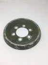
Sent my spinner away for repair and the front mounting holes were filled in. Thus, I need to match drill the spinner to the existing front spinner bulkhead mounting holes.

Looking for idea on the best way to match drill. Not sure something like this would work as space is tight.
 
Thus, I need to match drill the spinner to the existing front spinner bulkhead mounting holes.
What specific "front" holes are you referring to?
Is the spinner metal or fiberglass?
Has the spinner been repainted?
 
Not easy.

1way I’ve picked up blind nut plates is cutting off some screws of appropriate thread. You grind a point on the non- threaded end. Screw in with just a few thousandths above flush. Put Spinner on and tap area with a mallet to transfer mark.Alignment is the biggest issue here. It sounds like the rear plate is still proper which may help.
 
What specific "front" holes are you referring to?
Is the spinner metal or fiberglass?
Has the spinner been repainted?
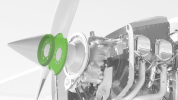
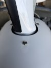
There are two sets of holes - one set (6 total) at the base of the spinner where the screws go into the rear bulkhead and another set (4 total), just forward of the prop cutout which attach the spinner to the forward bulkhead. Rear bulkhead holes are there, forward bulkhead holes need to be located and drilled.
Metal spinner.
Spinner has been stripped of paint. Will paint after drilling holes.

1way I’ve picked up blind nut plates is cutting off some screws of appropriate thread. You grind a point on the non- threaded end. Screw in with just a few thousandths above flush. Put Spinner on and tap area with a mallet to transfer mark. Alignment is the biggest issue here. It sounds like the rear plate is still proper which may help.
Had the same thought, but ...
How do you get the screw into the nut plate? They are the locking type and can't be screwed in with fingers.
How do you prevent the inside of the spinner from getting scratched?
 
another set (4 total), just forward of the prop cutout which attach the spinner to the forward bulkhead.
When you place the forward bulkhead into the spinner can you still see the nutplates on the bulkhead? If not, does the fwd bulkhead solid or have a hole in the middle?
Usually when there is a repair they should have relocated those holes for you.
 
That forward bulkhead is normally under the heads of the propeller bolts and re-locating the holes for its screws is a real pain. Impossible to see anything, and the taper of the spinner means that anything pointy sticking out of the anchor nuts in it will scratch the spinner, and will also hold the spinner further forward so that the holes end up aft of where they should be.

I'd be tempted to use a retrieval magnet with a very narrow magnet. Put the spinner on and feel around for the anchor nuts. That magnet should want to locate itself right over the center of the anchor nut. If it doesn't, it will want to locate over either end of the nut, and you might find a "null" over the screw hole. Experiment first with a magnet, a scrap of aluminum sheet, and an anchor nut fastened to a scrap of wood, flat side up. Or fool with it using that scrap of aluminum over the nut in the bulkhead; get the magnet located, then slide the aluminum out to see where the magnet centered.

You need a rare-earth magnet, common these days, and if it can be removed from the end of its shaft, so much the better.

1770595717506.png
 
Any way to get a hold of a scrap bulkhead that can cut & used as a template/fixture?
 
Is it a fixed pitch? It might be possible to remove the prop and install a spacer the same thickness as the prop. Install it with both your bulkheads in place and that may give you enough working room to use a hole duplicator. Any way you go, it’s going to be a PITA, but not impossible. “More th’n one way to skinna cat.”


*or send it back to whoever did the repair and make them redrill the holes they filled in.
 
Use dividers or calipers and two existing holes in the rear bulkhead to triangulate and locate the holes on the front bulkhead. Transfer those dimensions to the repaired spinner.
 
Possibly use bushings/tubing with same ID as bolt diameter and length equal to prop thickness to be a “ dummy prop”. Assemble using both plates.
It might give you room to gain access for marking.
Currently involved with something along these lines. Much modded PA-12
needs a front plate. No p/n markings and not in paperwork. I was going to ship to Univair with a dummy prop block. I did find the replacement though.
 
Is it a fixed pitch? It might be possible to remove the prop and install a spacer the same thickness as the prop. Install it with both your bulkheads in place and that may give you enough working room to use a hole duplicator. Any way you go, it’s going to be a PITA, but not impossible. “More th’n one way to skinna cat.”
That spacer would have to be exactly the same thickness as the prop. Exactly. If it isn't, the taper of the spinner means that it will be either too tight on the forward bulkhead, or too loose. Been there, done that enough times even with the OEM arrangements.

Besides that, we have two other problems:

1. The center hole in the aft bulkhead is often too small to work through anyway, and

2. The forward bulkhead is usually formed so that is flange faces aft and the anchor nuts are behind it. Those holes would be beside the spacer, completely out of sight even using a mirror. They often look like this:

1770602110019.png

How does one see those holes working through a hole in the aft spinner bulkhead?

This is the usual arrangement for a fixed-pitch installation:

1770602273555.png
 
Any way to get a hold of a scrap bulkhead that can cut & used as a template/fixture?
The holes in the spinner have to be perfectly indexed so that they line up with both sets of holes in both bulkheads. Both bulkheads are on the propeller bolts and their rotational positions are fixed.
 
Use dividers or calipers and two existing holes in the rear bulkhead to triangulate and locate the holes on the front bulkhead. Transfer those dimensions to the repaired spinner.
That might work but you'd have to be really precise. Better idea might be to use tracing paper, thin stuff so that it doesn't affect the fore-aft position too much, and tape it carefully onto both bulkheads, like a fake spinner with no point. Need to cut prop blade clearances into it too. Mark out the holes that will be visible though the paper, and tape that paper inside the spinner, lining up the aft bulkhead's hole marks on the paper with the aft holes in the spinner, and transfer via light punch marks to the spinner. You need to drill from the inside of the spinner, then, so one needs an angle drill or angle attachment.

Might be easier to start with the paper in the spinner, mark the aft bulkhead spinner holes on the paper, mark and cut the prop blade cutouts, then tape the paper to the prop/bulkheads assembly, lining up the aft holes with the bulkhead holes. Mark the forward bulkhead holes and then put the paper back in the spinner and punchmark the forward holes.

Taping the paper to the outside of the spinner won't work. The thickness of the spinner metal will shift the hole locations quite a bit.
 
That spacer would have to be exactly the same thickness as the prop. Exactly. If it isn't, the taper of the spinner means that it will be either too tight on the forward bulkhead, or too loose. Been there, done that enough times even with the OEM arrangements.

Besides that, we have two other problems:

1. The center hole in the aft bulkhead is often too small to work through anyway, and

2. The forward bulkhead is usually formed so that is flange faces aft and the anchor nuts are behind it. Those holes would be beside the spacer, completely out of sight even using a mirror. They often look like this:

View attachment 149729

How does one see those holes working through a hole in the aft spinner bulkhead?

This is the usual arrangement for a fixed-pitch installation:

View attachment 149730

The fwd bulkhead that I just looked at on a Piper Cherokee has the nutplate on the aft side of the fwd bulkhead, allowing access to the holes through the blade holes in the spinner.

Yes, spacer thickness would need to be same thickness as prop. That should understood.

I looked at my prop and thought it would be possible. Maybe it is, maybe it isn’t.

I’d still be more inclined to send it back to the shop that filled the holes and make it their problem.
 
I’d still be more inclined to send it back to the shop that filled the holes and make it their problem.
No can do. How is the shop supposed to know exactly where to put the holes? Any offset from exactly centered over the nut plate and you introduce stress due to the "persuasion" needed to get the holes lined up.

The holes have to be matched drilled to bulkheads as installed on the plane. The shop is in another state and can't get the plane there.

Use dividers or calipers and two existing holes in the rear bulkhead to triangulate and locate the holes on the front bulkhead. Transfer those dimensions to the repaired spinner.
Maybe. Issue here is the rear bulkhead holes are oversized and the whole sizes aren't uniform. So, I'd have to factor that in when laying out. Have to think about this one.

Better idea might be to use tracing paper, thin stuff so that it doesn't affect the fore-aft position too much, and tape it carefully onto both bulkheads, like a fake spinner with no point. Need to cut prop blade clearances into it too. Mark out the holes that will be visible though the paper, and tape that paper inside the spinner, lining up the aft bulkhead's hole marks on the paper with the aft holes in the spinner, and transfer via light punch marks to the spinner. You need to drill from the inside of the spinner, then, so one needs an angle drill or angle attachment.
This idea might have some legs. Easy enough to put some tape on the inside of the spinner near where I think the holes would be. Trick would be to find a way to mark the hole locations from behind with the spinner installed. But how ????? Need to go back out the hangar and take a closer look at that forward bulkhead and see if there is a way to get to the rear of the nutplates.

I'd be tempted to use a retrieval magnet with a very narrow magnet. Put the spinner on and feel around for the anchor nuts. That magnet should want to locate itself right over the center of the anchor nut.
Another intriguing solution. If I can find a small cylindrical magnet that would slide into the nut, then with the spinner installed a small steel disc or ball bearing should located itself directly over the center of the nut. Gotta noodle on this one.


Keep the ideas coming.
 
From the diagram that Dan put up, and your description, the base mounting holes are done and line up, and it's the front ones that you don't have. And you can't use stud with a point on it to mark the inside of the spinner because that would scratch the spinner and the spinner wouldn't seat fully.

What if you put some kind of plastic stud, maybe a nylon screw that you sharpened to a gentle point, in the front screws. Then put carbon black or something inside the spinner, and slowly slide the spinner on. If it barely touched that should give you radial alignment from the inside of where the holes would be. That might not help a lot, because the marks would be on the inside, and you'd have to be sure the base was fully seated to get the long dimension right.

The other thing that comes to mind is along the lines of the tracing paper idea, but making a partial spinner cover with a 3D printer. Or maybe even carefully over mold a piece of fiberglass over the spinner with it connected in back. Like a T shaped section, located on two of the bolts in the back at the top of the T, with the bottom of the T being roughly where the front bolt goes. Then remove the spinner, create a spacer that matches the base of the spinner, then mark on the over molded piece where the front hole goes, and transfer that mark back to the spinner. That would be a PITA, and you'd need to make four little arm like things, one for each hole, but I think it might work.

Oh, third idea that won't work: Make some kind of plastic James Bond device that your screw into the front holes that is flush. That's set to a 15 minute delay before it shoots something sharp out the top. Put the spinner on, stand clear and wait for the pilot holes to be blown through for you. If this idea works, I want a copy of the video.
 
Do you have access to a 3d printer? Take a straight on picture of what you want to match drill to theb use an online photo editor to convert it to a line drawing, theb use that drawing to create a svg file and then import that into your favorite cad program and scale it to size. Once you have that you can make all sorts of jigs to accurately match drill other parts.
 
Fixture to hold a laser pointer?

Set it up with the laser on the hole, slip the spinner on and mark it?

I'd use some .032 or heaver sheet, drill a hole in it and center it on the laser beam, tape/clamp it firmly in-place and use it as a drill guide.
 
Keep the ideas coming.
Since it appears the bulkheads are installed, get some very thin clear acrylic sheets and locate/install them across the bulkheads. Drill the holes the same size as the screws and tighten. Once the sheets are installed, tape the edges to keep them indexed and remove screws. Place pattern on spinner and secure rear edge with hardware then locate forward holes by marking or drilling pilot holes. Step drill the holes to ensure they are centered properly.
 
What specific "front" holes are you referring to?
Is the spinner metal or fiberglass?
Has the spinner been repainted?
Ones like these on my MT attaching the spinner to the forward spinner bulkhead:
 

Attachments

  • IMG_1418.jpeg
    IMG_1418.jpeg
    1.2 MB · Views: 7
Post a picture of your spinner and the front mounting area you need to have the holes, as well as where you will mount it. Might help to better visual what you have.
 
A Partial solution - If the spinner is formed from a flat sheet conically formed (rather than compound formed) rather than using paper as a template for transferring holes, use drafting Mylar. The one version I have used for such monkey business is shiny on one side, fully transparent, and has a very slight roughness on the other side which takes a 4H pencil marking. Being able to have some stiffness and being very dimensionally stable is important. The sheets I have are "D" size and .0032" thick. I could mail you a folded sheet.

Sounds like a fun challenge. Won't work for a compound formed spinner.
 
Last edited:
I'm still trying to figure out how they plugged the holes without leaving a trace of where they had been.
Welded? New sheet metal? Replace the whole thing?
 
Gosh I hope this isn't K&K, I've been using them forever and never got back a "blank" spinner like that :/

GL? I have no idea how to deal with that.
 
Ball shaped rare-earth magnets like Neodymium (NdFeB) and carbon paper.
 
Fixture to hold a laser pointer?

Set it up with the laser on the hole, slip the spinner on and mark it?

I'd use some .032 or heaver sheet, drill a hole in it and center it on the laser beam, tape/clamp it firmly in-place and use it as a drill guide.
That's brilliant. To make the fixture, all you need is a little piece of wood or something with a groove in it, tape or zip tie or rubber band a laser pointer to that. Then put a 1/4 nut or insert or whatever on the wood, and screw that onto a tripod. Standard tripod thread is 1/4-20. Put a piece of masking tape over the screw hole to make a target, put the pointer in line with the hole so there's no parallax error, mark it on the spinner with a fine point sharpie. Way better idea than I had.
 
Last edited:
A Partial solution - If the spinner is formed from a flat sheet conically formed (rather than compound formed)
The only spinner I ever saw that was formed (rolled up and riveted along the seams) from flat sheet is one I made for a Subaru conversion. Spinners are almost always formed in a lathe over a die. It starts as a flat sheet alright, but it is coaxed into a cone or bullet shape using steel bars and lots of pressure. Same way that bells for musical wind instruments are formed.

 
I'm still trying to figure out how they plugged the holes without leaving a trace of where they had been.
Welded? New sheet metal? Replace the whole thing?
Yes, repairs were done by a certified welder. The welder simply filled in the holes and ground smooth. A very common welding procedure.

I specifically asked the welder to fill all the forward holes so they could be redrilled as this was the second time I've had a crack start at one of the forward bulkhead holes. Time between cracks was less than 50 hrs. The forward holes never quite lined up and I had to "persuade" things to get all the holes lined up. I'm pretty sure this put a sheer stress on the side of hole which was relieved by cracking.

I want to be able to slip the spinner on and have all the holes line up without having to force anything.

Fixture to hold a laser pointer?
Brilliant!

Winner Winner Chicken Dinner

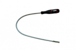
Thinking of using a flexible shaft off this inspection mirror (https://www.harborfreight.com/2-inch-mirror-with-flexible-shaft-97217.html) and taping one of those keychain lasers to the mirror end. Easy enough to secure the other end to the prop with tape. This will give me lots of flexibility to properly aim the laser through the nut plate. Install the spinner on the rear bulkhead without disturbing anything and mark the spot indicated by the laser. Voila!

I'll post pics.
 
The only spinner I ever saw that was formed (rolled up and riveted along the seams) from flat sheet is one I made for a Subaru conversion. Spinners are almost always formed in a lathe over a die. It starts as a flat sheet alright, but it is coaxed into a cone or bullet shape using steel bars and lots of pressure. Same way that bells for musical wind instruments are formed.
The technique is called metal spinning. https://en.wikipedia.org/wiki/Metal_spinning
 
Very familiar w it. There is a single welded longitudinal seam on the inside of the conical Cessna spinner, so it could be formed from a flat sheet. It would be hell to spin-form over that seam. Bet someone worked on that one a long time.....
 
I'd go with the laser. It would be universal, but fixturing should be metal and referenced to the engine case.
 
I'd go with the laser. It would be universal, but fixturing should be metal and referenced to the engine case.
I like that idea of referencing to the case.

I might even consider a second laser pointing to a hole/nutplate combo that is drilled (piece of tape or something on nutplate so laser shows up) as a confirmation that nothing moves when the spinner gets slid on.

Maybe unnecessary.
 
I have worked on a lot of Cessnas, including inspecting the spinners when prop work is necessary, and have never seen any such seam in any spinner. Those spinners are formed the same way as in that video.
 
Brilliant!

Winner Winner Chicken Dinner

I'll post pics.
So.... Line up laser to one of the forward holes, attach spinner with rear bolts, mark the first forward hole, remove spinner, rotate prop and line up next hole, rinse and repeat? Clever. Looking forward to your pics.

EDIT: Had a flash back to the James Bond Goldfinger movie with the laser powerful enough to cut metal. "No Mr. Bond, I expect you do die"
 
Last edited:
Ball shaped rare-earth magnets like Neodymium (NdFeB) and carbon paper.
Works great with composite spinners. Hundreds of VANS RV spinners placed with. Might be less accurate with Al3+ spinners though.
 
Works great with composite spinners. Hundreds of VANS RV spinners placed with. Might be less accurate with Al3+ spinners though.
Why? Aluminum is not magnetic. It will not impede the magnetic field unless that field was moving with respect to the aluminum.
 
Not that relevant to your spinner but I've been match drilling a bunch of Cessna tips the last few years, the last set was attached with machine screws. Take a couple flat straps of .032 aluminum scrap and drill a hole in it that fits the screws well, attach the straps to the screw holes with washer roughly the same thickness of the fairing to be drilled, tape the strap firmly to the stabilizer/rudder/elevator etc using aluminum tape, remove the screw and washer, slip the fairing on verify edge distance you want and drill it.

Before all that, slip fairing on and position it where desired and tape some stop blocks along the lap joint to the stabilizer/rudder/elevator etc so that each time you R&R the fairing as you progress with match drilling process the fairing positioning is easily repeatable.

It takes a little time but the results are better than a typical strap duplicator or hole finder IMHO.

In reality you could use this process on your spinner but you need a good solid thing to tape a strap to, like a step ladder with a sandbag on it or something,

I was kinda looking at something like a machinists dial indicator holder with a laser pointer on it
 
Last edited:
Pics, descriptions and results, as promised.

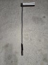
Pic 1
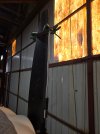
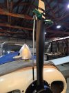
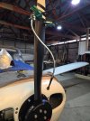
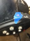
The tool was constructed using a piece of angle iron, a metal gooseneck, and a laser pointer. Goosneck had a threaded end on it so it was just a matter of drilling a hole in the angle iron and attaching. Laser pointer was just taped to the other end of the gooseneck. The white lines on the angle iron is weatherstripping used as padding.

Pic 2 & 3
The tool was mounted to the backside of the prop using two small, padded bar clamps.

Pic 4
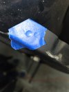
Tape was placed over the nutplate hole and rubbed with finger. This created a divot used for positioning laser.

Pic 5
The tool positioned to mark location of nutplate.

Notes: The laser pointer had a momentary button to activate. I used a small adell clamp, slipped over the end, to act as a clamp to keep the button depressed. You can see that at the very end of the pointer in the pic. Also, I didn't turn the laser off between markings and ran the batteries down after two holes. The batteries most likely would have lasted if I turned the laser off between markings.

Pic 6
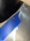
Closeup of the laser point in the center of the divot.

Pic 7
Marking of the laser location on the spinner.

Notes: Once the laser was located, the spinner was carefully mounted and secured in place, being careful not to move anything. A mark was then made on the spinner. Once the spinner was marked, the mounting screws were removed and the laser checked again to see if location was still accurate. If not, do over. (I only had to that once on the first hole.) The pic shows the mark on a piece of tape but for the remaining holes I just marked directly on the spinner. Doing this made the mark easier to see.

Pic 8
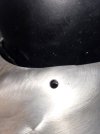
The results was perfect match drill. The camera was not directly over the hole so it appears to be off center, but I can assure you the screw went in without any difficulties.

Rinsed and repeated for the remaining three holes.
Pic 01 (1).jpgPic 02.jpgPic 03.jpgPic 04.jpgPic 05.jpgPic 06.jpgPic 07.jpgPic 08.jpg
 
Back
Top