Cessna 152 Low Volt Light Frustration

Ventucky Red

En-Route
PoA Supporter
Joined
Jan 9, 2013
Messages
2,595
Display Name
Jon
Home Airfield
KCMA
So, new battery voltage regulator (alternator control unit), and rebuilt alternator and still having an intermittent issue with low voltage... that is we're only getting 24.5 volts at 2300 rpm when we should be getting 27.5. This is an issue as if I put on any lights, etc.... it drops and on comes the light...

When we changed the battery, it worked well for a couple of hours then here were are back to the problem again. My A&P and I looked at it together and when we put the new battery in it went away and we thought we solved the problem.. not so. The alternator control unit has and adjuster, played with that, and again, once the new battery we though we solved the problem.

Are there any other things I should look to test and/or replace? The solenoid that the battery positive wire connects to... could that have gone bad and does this play into the equation?

Any other suggestions?


Thanks..
 
Have you considered replacing parts at random until the problem is fixed? :)

There are lots of threads here about electrical gremlins, and the answer is always the same: stop and troubleshoot things before breaking out the parts shotgun.

In your case, you may get to replace your battery again unless you address the root cause.

@Dan Thomas will be along to offer actual constructive advice.
 
Alternator circuit breaker is bad, and has excessive voltage drop? Or the wiring between the alternator and the breaker? Or the alternator ground?

Use a multimeter (and extension wires/ring terminals) to measure the voltage drop between those points with the engine running.
 
I'm fighting one as well. 12 volt - 60 amp belt driven (Ford style) with external voltage regulator.

In flight it would drop offline, so I'd shut all electrical power off and turn it back on, it would charge a few minutes and drop out again.

On the ground I was able to make it fail but all I had hooked up at the time was a multimeter to the main bus checking for AC voltage (alternator rectifier leakage) and didn't find a smoking gun.

I think next going to clip onto the field terminal at the alternator and see if I can catch that dropping out, if no smoking gun there clipping onto the main 60 amp breaker for voltage drop.
Cessna? This sounds like an OV sensor failure. Even if you have an aftermarket VR installed, it's quite possible that they left the original OV sensor installed and it's now malfunctioning and taking the field power offline.
 
Last edited:
So, new battery voltage regulator (alternator control unit), and rebuilt alternator and still having an intermittent issue with low voltage... that is we're only getting 24.5 volts at 2300 rpm when we should be getting 27.5. This is an issue as if I put on any lights, etc.... it drops and on comes the light...

When we changed the battery, it worked well for a couple of hours then here were are back to the problem again. My A&P and I looked at it together and when we put the new battery in it went away and we thought we solved the problem.. not so. The alternator control unit has and adjuster, played with that, and again, once the new battery we though we solved the problem.

Are there any other things I should look to test and/or replace? The solenoid that the battery positive wire connects to... could that have gone bad and does this play into the equation?

Any other suggestions?


Thanks..
Some quality time with a multimeter will likely track this down fairly quickly. There are a number of things it can be, but my WAG based on the parts cannon you've unloaded so far is voltage drop on the output path from the alternator.
 
Cessna? This sounds like an OV sensor failure. Even if you have an aftermarket VR installed, it's quite possible that they left the original OV sensor installed and it's now malfunctioning and taking the field power offline.
Pretty sure it doesn't have an external OV sensor (1968 Cessna 182 no OV light) but the field could still be cutting out and should be easy to catch it in the act.
 
Are there any other things I should look to test and/or replace?
Has any basic troubleshooting been performed like voltage drops, continuity checks, visual/tactile inspection of all connections, etc? If not, I'd find a schematic for your system and start there before reloading the parts cannon again.
 
Have you considered replacing parts at random until the problem is fixed? :)

There are lots of threads here about electrical gremlins, and the answer is always the same: stop and troubleshoot things before breaking out the parts shotgun.

In your case, you may get to replace your battery again unless you address the root cause.

@Dan Thomas will be along to offer actual constructive advice.


I hear ya on the parts cannon... the alternator was done at annual two years ago - a lot of corrosion, the regulator a year and a half ago when I upgraded the panel, and the battery recently... after the problem became an issue... the old battery was over 15 years and did a lot of sitting.

I bring this up for the process of already eliminating some of the common causes..

Thanks for your help - appreciate it.
 
Often overlooked is the Field CB and the ALT side of the Master.
These may be nearing 50 years old. Current to excite the Field passes through both of these. Agree with comments to use a meter rather than wallet.
 
...visual/tactile inspection of all connections...
:yeahthat:

I cannot unsee the things I saw when I first stuck my head under the panel, but I'm glad I did.

The tactile part is important. I had a recent gremlin where my ALT INOP light flickered. The field wire was secured to the field breaker... but the lug on the breaker itself wiggled like a loose tooth. That was the issue.
 
What about real basic stuff like connections, grounds, wires etc?
 
What about real basic stuff like connections, grounds, wires etc?

Yes, this is on the elimination list... will be going through this shortly... goes back to my old VW days with corroded grounds.

Thanks
 
and rebuilt alternator and still having an intermittent issue with low voltage
Most likely it's this "rebuilt" alternator. More on that in a minute.
@Dan Thomas will be along to offer actual constructive advice.
Here I am, and the advice will be the same as it usually is.
Cessna? This sounds like an OV sensor failure. Even if you have an aftermarket VR installed, it's quite possible that they left the original OV sensor installed and it's now malfunctioning and taking the field power offline.
He gets a voltage drop when he loads up the alternator. That means that the alternator can't keep up. More on that in a minute. The overvolt sensor shuts the regulator off if the voltage rises too high, lighting the panel light that was variously labelled "over voltage" or "low voltage," depending on the year. There was no difference in the system or function. That light will come on if the Alt switch is turned off, or if there is loose wiring or connectors or a bad switch or breaker in the Alt switch circuit. It will not come on if the alternator just quits, like it does in a car. The alternator could fall right out of the airplane and the light wouldn't come on. The modern ACUs (alternator control units) fix that.
Often overlooked is the Field CB and the ALT side of the Master.
These may be nearing 50 years old. Current to excite the Field passes through both of these.
The field current doesn't pass though the Alt switch or breaker. All that field switch does is turn the regulator on. The regulator has an "A" terminal and a wire goes from that to the alternator output stud, same stud that has the fat output cable on it. That A terminal feeds two things in the regulator: the voltage regulator relay coil, and it also provides the current for the field via the regulator relay contacts.

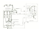
One has to get a look at the whole alternator-regulator circuit to understand it:
1757978944142.png

This drawing leaves out the master contactor and switch. I adapted it from the Ford car/truck system. The Alt switch is between the bus (battery) and the S terminal on the regulator, and you can see that it does nothing but turn the regulator's field relay on. The field current itself comes from the A terminal which, in the Cessna is connected to the alternator output. In a Piper it often goes to the bus. It gets the same information from either place. The field relay connects that to the voltage limiter relay via some resistors and stuff, and it goes through the limiter relay contacts and to the field in the alternator. When the voltage rises to the regulator setting, the contacts are pulled open and the field is shut off. The system voltage falls, the contacts close, and the voltage rises again. This happens hundreds or thousands of times a second. Even the newer electronic regulators use the off-on method of regulating. The field coil in the alternator smooths the flow, and the shutoff isn't total since the field is still connected to the system via the 10-ohm resistor. There are usually a couple of capacitors in the system to kill the electrical noise generated by that limiter relay and the field itself.

The alternator generates power using electromagnetism. Any time a magnetic field moves through a coil of wire, electron flow is generated is that coil. In the alternator, the magnetism comes from the rotor that is spun by the engine via a belt and pulley, or gears. The field current generates that magnetism in the rotor's coil, and more current means a stronger magnetic field. The alternator's output is dependent on three things: (1) the number of turns of wire in the stator (output) coils, which is something we can't change. (2) the speed of the field's movement, and in this case it's the speed of the rotor, which is directly related to the engine RPM. (3) The strength of the rotor's magnetic field, which depends on how much current the regulator feeds it. This is the handiest way to control the output of the alternator. As more loads are switched on in the airplane, the system voltage will fall and the regulator will feed more current to the rotor's field to strengthen the magnetism and make the alternator produce more current, keeping the system voltage up.

So electrical current has to be fed to that spinning rotor somehow, and it's done with carbon-block "brushes" that don't look anything like any brush. They ride on copper slip rings attached to the rotor shaft, and those slip rings are connected by wires to the rotor's field coil.

Now, to the real problem: that "overhauled" alternator. It will be a Ford alternator, DOFF10300-something. The Ford alternator has its slip rings immediately next to the rear bearing, which is a Torrington cup-type needle bearing with tiny rollers in it, lubricated by a tiny amount of grease. But the overhaulers all seem to make the same stupid mistake: they put a big gob of grease in there, and when the alternator is assembled and the rotor shaft goes into the bearing, much of the grease is squeezed out and it gets flung around by the spinning slip rings and gets on them. It mixes with carbon from the brushes and makes a tough sludge on those slip rings that presents a resistance to the electron flow from the brushes to the rotor's field coil. Now, no matter what the regulator does, it cannot feed enough current to the rotor to make its field strong enough to generated enough power in the stator coils to keep the airplane's system voltage up when additional loads are put on it.

I found this problem countless times in "overhauled" alternators, never in a brand-new alternator. The factories know what they're doing, and they even publish manuals that overhaulers are supposed to use on certified aircraft components. Kelly Aerospace was awful for this, then Hartzell, who bought them, and now I think it's Boeing, but the overhauling won't be done by Boeing techs. I filed endless SDRs on the problem, but nothing ever got fixed. There are also many independent overhaulers that make this mistake, too. It got so bad that I was taking apart overhauled alternators before I even installed them. I cleaned up all that grease, cleaned the slip rings and brushes. Then the thing worked like it was supposed to.

To find out if this is the problem, disconnect the field wire from the alternator. Disconnect all the spark plugs, too. Put an ohmmeter across the field terminal and the alternator case, and you should find something in the neighborhood of 8 to 11 ohms for a 24-volt alternator, and that resistance should remain steady when you turn the propeller. If it's much higher than that, or if the resistance jumps around when the prop is moved, you have a grease problem. The resistance for a 12-volt alternator is about 3 to 5 ohms.
1757982266604.png

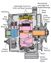
A side view of an alternator similar to the Ford. The slip rings are the blue things on the left. They're on the rotating shaft. The field brushes ride on them but they're not clearly shown here. There are light springs that keep them in contact with the slip rings. The rear bearing has that green shaft in it, which is just the same shaft as the rest of the orange thing that the pulley spins. Too much grease in that bearing just gets extruded when the shaft enters it. There should be just enough grease in there to fill the spaces between those tiny rollers in the bearing, nothing more.

That alternator in a car is usually running at about a third of the RPM it runs in the airplane, since in both cases they are geared or pulley-ratioed so that they reach their redline when the engine reaches its redline. The car is loafing along at a third of its redline, the airplane is at 90% of its redline. Those brushes therefore wear out much faster, which is why the alternator manufacturers recommend 500-hour brush inspections, and its also why those owners that ignore those recommendations have alternator failures when the brushes get too short and pop out of the their guides and the field dies. No more output. And a trashed alternator, since the springs then arc on the slip rings and ruin them, and you're buying another $700 alternator instead of replacing $30 brushes.

 
Last edited:
I'm fighting one as well. 12 volt - 60 amp belt driven (Ford style) with external voltage regulator.

In flight it would drop offline, so I'd shut all electrical power off and turn it back on, it would charge a few minutes and drop out again.

On the ground I was able to make it fail but all I had hooked up at the time was a multimeter to the main bus checking for AC voltage (alternator rectifier leakage) and didn't find a smoking gun.

I think next going to clip onto the field terminal at the alternator and see if I can catch that dropping out, if no smoking gun there clipping onto the main 60 amp breaker for voltage drop.
See if it drops offline when you key the Com transmitter. If your airplane has an Alternator Control Unit instead of an older regulator, any RF leakage from the antenna cables or their connectors will send RF into the aircraft's system wiring and that sensitive ACU interprets those sharp little voltage spikes as an alternator problem and shuts itself off, killing the alternator too. Look for loose or corroded coax connectors, especially in the ceiling above the headliner where moisture from the breathing of the occupants condenses and gets into the connectors.

Edit: The other thing to check is the OV sensor's ground wire connection to the airframe. If it's loose, the sensor intermittently loses its ground reference and it gets confused and shuts the regulator off.
 
Last edited:
M

One has to get a look at the whole alternator-regulator circuit to understand it:

Hi Dan.. Very much appreciate your help..

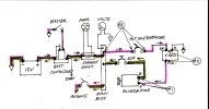
Does this look to be right regarding a 152? That for charging the battery that runs the electrical system I understating that the voltage goes from the alternator > breaker > buss bar > current shunt (which has been replaced) > solenoid > battery to recharge?

wiring1-1924099423.jpg
 
See if it drops offline when you key the Com transmitter. If your airplane has an Alternator Control Unit instead of an older regulator, any RF leakage from the antenna cables or their connectors will send RF into the aircraft's system wiring and that sensitive ACU interprets those sharp little voltage spikes as an alternator problem and shuts itself off, killing the alternator too. Look for loose or corroded coax connectors, especially in the ceiling above the headliner where moisture from the breathing of the occupants condenses and gets into the connectors.

Edit: The other thing to check is the OV sensor's ground wire connection to the airframe. If it's loose, the sensor intermittently loses its ground reference and it gets confused and shuts the regulator off.

Ran it last night with a multi-meter clipped onto the field terminal at the alternator, when charging puked there was zero voltage on the field terminal. I tapped on the master switch and other stuff and it made no difference. I have a brand new Zeftronics R15100 without the internal OV protection. I pulled the connector off the old one and found the cessna wiring terminals sloppy loose fitting on the new regulator, it was late so I didn't get any further.

To open a whole new can of worms - WHY do the pre-1972ish Cessna not have an external OV sensor, it sure doesn't look like any of them had internal OV protection built into the regulators then either. This makes little sense to me. I don't get the evolution of the over voltage protection and the vendor data on which part numbers are required on which systems stinks.

Both Cessnas (1968 model years) we have are the NOT split master switches, no alternator field circuit breakers on the panel, and no voltage warning lamps. Both have 60 amp Ford type alternators with the external regulator. Are we expected to install the internal OV on the ones that don't have other OV protection?
 
I don't get the evolution of the over voltage protection
It was explained to me that evolution followed the move from generators to alternators. Generator control systems tended to be very basic. With the install of alternators, they typically had higher outputs and different failure modes vs a generator system. So, in the case of Cessna and other OEMs, they upgraded the old generator-based control systems and went to a split switch, overvoltage protection, etc. to handle these different failure modes and operational issues.
 
So, new battery voltage regulator (alternator control unit), and rebuilt alternator and still having an intermittent issue with low voltage... that is we're only getting 24.5 volts at 2300 rpm when we should be getting 27.5. This is an issue as if I put on any lights, etc.... it drops and on comes the light...

When we changed the battery, it worked well for a couple of hours then here were are back to the problem again. My A&P and I looked at it together and when we put the new battery in it went away and we thought we solved the problem.. not so. The alternator control unit has and adjuster, played with that, and again, once the new battery we though we solved the problem.

Are there any other things I should look to test and/or replace? The solenoid that the battery positive wire connects to... could that have gone bad and does this play into the equation?

Any other suggestions?


Thanks..
It sounds like high resistance in a wire to me. The regulator senses voltage and outputs power to the alternator field to build amps and voltage. If that wire warms up and restricts the current the voltage can go down, or up depending on what circuits are affected. Have you tried running some bypass wires around the system to see if it improves?
 
Hi Dan.. Very much appreciate your help..

Does this look to be right regarding a 152? That for charging the battery that runs the electrical system I understating that the voltage goes from the alternator > breaker > buss bar > current shunt (which has been replaced) > solenoid > battery to recharge?

View attachment 145221
Yup. That's correct.
 
Hi Dan.. Very much appreciate your help..

Does this look to be right regarding a 152? That for charging the battery that runs the electrical system I understating that the voltage goes from the alternator > breaker > buss bar > current shunt (which has been replaced) > solenoid > battery to recharge?

View attachment 145221
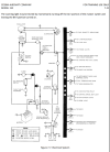
Here is the electrical diagram from the 152 POH:

1758769649489.png


Note that there is a self-resetting breaker between the alternator output breaker and the ALT switch and overvolt light. That breaker might be a source of your problems. You will find it mounted somewhere under the panel, not on the pilot's side of the panel.
 
Is the battery in a C152 in the tail? If it is, has anyone checked the impedance of the long, nearly 50 year old, battery cables?

And over the years, was there ever a repair to the battery cable? A long shot, but maybe there's a corroded connection somewhere along the run.
 
Here is the electrical diagram from the 152 POH:

View attachment 145443


Note that there is a self-resetting breaker between the alternator output breaker and the ALT switch and overvolt light. That breaker might be a source of your problems. You will find it mounted somewhere under the panel, not on the pilot's side of the panel.

Hey Dan... thanks.. I saw that too and wondered if this or the battery contactor could be contributing to the problem. We'll be checking it out this weekend and I'll let you know the what we uncover.

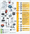
Found this diagram - which is similar. However, neither show the current shunt which is between the primary bus and the battery contactor the feeds to the ammeter. I am wondering if there is an either/or for this depending on the serial number.

Appreciate your time


c1aj4.jpg
 
Found this diagram - which is similar. However, neither show the current shunt which is between the primary bus and the battery contactor the feeds to the ammeter. I am wondering if there is an either/or for this depending on the serial number.

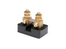
In most Cessnas the shunt is built into the ammeter itself. Do you have a separate shunt somewhere? Looking something like this?

1758818606170.png

If you have two thick wires or cables attached to the ammeter studs, the shunt is internal. An external-shunt ammeter will have a couple of thin wires to it.
 
In most Cessnas the shunt is built into the ammeter itself. Do you have a separate shunt somewhere? Looking something like this?

View attachment 145459

If you have two thick wires or cables attached to the ammeter studs, the shunt is internal. An external-shunt ammeter will have a couple of thin wires to it.

I believe that is what we replaced last spring, my A&P did it. I'll go look to see

Mr. Google did educate me in the difference between the shunt and what an alternator field circuit breaker does.. I'm a learning...

Would it be possible to have both a shunt inline feeding the ammeter, and one internally in the ammeter? Previous owner was a tad bit of a shade tree mechanic and who knows!!
 
Back
Top