
Wind triangles?

drummer4468

Pre-takeoff checklist
Joined
Jul 5, 2020
Messages
325
Display Name
drummer4468
Potentially dumb question/request for sanity check:

Currently brushing up with Sheppard to retake my FIA exam (due to the previous one expiring a few years ago) and came across some material regarding wind triangles. As in a graphical representation of wind correction.

To ask bluntly, is this a newer teaching concept? Or have I discovered a weird hole in my training? Because I don’t recall ever drawing or deciphering a wind triangle before now. I’ve always used the “boat traveling across the flowing river” analogy and it’s always gotten the point across (pun somewhat intended).

I’m proficient at calculating wind correction, and I grasp the concept of graphically drawing it out. But try as I might, the way the FAA forms/labels the graphic and questions makes absolutely zero sense to me. Felt like a boomer trying to figure out his grandkids’ “new math” homework last night lol.
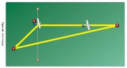
1791030580627.jpeg
The practice question I was getting asks me what like A-B represents, which i (incorrectly) interpret as desired ground track. Not really sure how to interpret the placement of the two airplanes. It’s all very abstract to me.
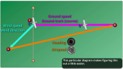

1791029963313.png

This image I found online is supposed to make it easier, but I still don’t grasp the structure of this concept.
 
The wind triangle and a slightly older than dirt. The E6B was designed to make it simpler.

The way you use a wind triangle is to plot your course, in these examples, 090.
Plot the wind from your same starting point at C, in this case, say from 045 degrees at 15 knots.
Take a compass or dividers and open it to the number of miles you fly in an hour (your TAS.)
Place one point of the dividers on A. Where the other point intersects your course line (B) is the distance you’ll travel in an hour (your GS.)
Measure angle ABC…that’s your wind correction angle.
 
The wind triangle and a slightly older than dirt. The E6B was designed to make it simpler.
I took the Private Pilot written when I was 15. Didn't have a E6B, brought in a ruler and protractor and solved the problem graphically.

It *does* give you a better understanding of the physics involved.

Ron Wanttaja
 
This is an instance where test-taking skills can come in really handy, as the question and figure give away the answer. The test creators have given you a massive hint. You should be able to answer this without knowing beans about a wind triangle or how to use an E6B or calculate a heading. Notice that they've drawn the airplane with its longitudinal axis parallel to the AB line.

1791042419915.png​

That should make it pretty clear that AB represents the plane's heading and airspeed. It's then pretty obvious that CA represents the wind, so CB must be the ground track. And if that weren't enough, they depict the plane flying along CB, so it must be the ground track.
 
It's a very old teaching concept. It's always been a good graphical way of explaining wind correction. I learned it as a student pilot 36 years ago and used it when I started teaching 27 years ago. As mentioned, it's the underlying basis of the E6B wind side. Is that old enough? :D
 
My high school sophomore daughter came to me with one of these in her physics homework a week or two ago.
Oh, I've got you! I thought....
oh wait, it's been a while....;)​
had to think for a minute....

I even thought about going to grab my E6B but then I thought better...I'd have to scratch my head to remember how, and we had no time. she was scrambling out the door to catch her bus

hers was drawn with the destination at the top, and the wind was from a known angle, 52 degrees or something....
then I was well into my "lesson"
which was all centered around the assumption that up is North, so that's your zero degrees....
and she interrupts telling me the the teacher does everything with zero on the right....
that made me pause a moment to wrap my head around that.... so I shrugged and said well I suppose your teacher isn't a pilot or a boat captain...
then I proceeded to spin my "chart" 90 degrees.... o_O

edit...I meant to add. I honestly don't recall that presentation of a triangle drawn like that in pilot training either, although I'm sure that it was. The way I remember it would have been a figure like that showing the course from A to B. Point C would have depicted where you'd end up if you didn't crab into the wind, which would have been coming from the South generally.... but it does break down the vectors and angles
 
Last edited:
I got one word…

MO BOARD

Tools
And one prolonged blast, anchor’s aweigh!
 
I did my private pilot groundschool while I was in college. The instructor was Cal Walker, a physics professor and accomplished glider pilot. He says, OK, you guys all have scientific calculators and are smart, so I'm just going to teach you how to do the wind calculations with vector math. A calculator and knowledge of the law of cosines is really all you need. I didn't buy an actual E6B until I was getting ready to start my flight lessons. While playing with the thing after buying it at the FBO, I'm realizing, hey, this is just a slide rule. I was just in the era where things were moving from sliderules to things like the HP65.
 
If you ever worked the wind problems counting lines and dropping little pencil marks on the rotating plastic on the back of your E6B, then you were doing exactly this.

I am curious, how did you learn this information?
 
Potentially dumb question/request for sanity check:

Currently brushing up with Sheppard to retake my FIA exam (due to the previous one expiring a few years ago) and came across some material regarding wind triangles. As in a graphical representation of wind correction.

This image I found online is supposed to make it easier, but I still don’t grasp the structure of this concept.
It tells you how to use wind triangles in the PHAK...
 
Well... it seems I did, in fact, find a hole in my training lol. Or at least experience. I did learn on the E6B first and got a good handle on it, before transitioning to the CX-3 later on in private training. But even while using the whizwheel I never actually drew or used wind triangles. I just used a little dot on the plastic then rotated and slid it around to make the calculations. Looking back at instructional videos as I type this, I can see how it would generate the pattern depicted above. I guess I just wasn't used to seeing the lines, labels, and little airplanes as laid out in the graphic
 
This image I found online is supposed to make it easier, but I still don’t grasp the structure of this concept.
It is a way to divide the effect of wind drift and aircraft travel through the air into two separate steps: Point "A" is how far you would drift if you were in a hot air balloon after one hour, resulting in a new starting place; The second airplane is positioned at a one-hour radius from Point "A". That could be anywhere on a circle from "A", but since you want to be on course for "B" in an hour, your position at that time will be where your desired course and radius of action cross.

Well, I see I'm late to the party. Shucks.
 
Last edited:
It is a way to divide the effect of wind drift and aircraft travel through the air into two separate steps: Point "A" is how far you would drift if you were in a hot air ballon after one hour, resulting in a new starting place; The second airplane is positioned at a one-hour radius from Point "A". That could be anywhere on a circle from "A", but since you want to be on course for "B" in an hour, your position at that time will be where your desired course and radius of action cross.

Well, I see I'm late to the party. Shucks.
That explanation helps it make more sense. I had similar thoughts when I was trying to understand it at first, but my brain kept getting stuck on "this is a whole lotta lines and points to illustrate a relatively simple calculation/concept,"

I'm sure it helps some others' brains to illustrate it this way. I simply learned a different method and never looked at this one, so I was utterly confuzzled at not understanding a basic wind correction question while brushing up for a flight instructor written. I didn't use Sheppard last time so I never encountered these specific questions. Not that I remember anyway.
 
If you ever worked the wind problems counting lines and dropping little pencil marks on the rotating plastic on the back of your E6B, then you were doing exactly this.

I am curious, how did you learn this information?
I learned on the E6B, but never drew lines or triangles. I simply placed my single dot and rotated/slid it around to make the calculations. I never processed it as "making a wind triangle". Just letting the slide rule work its magic.
 
I remember this method from college 40 years ago. Can't remember if it was covered in math or engineering; maybe both?
 
That explanation helps it make more sense. ...but my brain kept getting stuck on "this is a whole lotta lines and points to illustrate a relatively simple calculation/concept,"

...I was utterly confuzzled at not understanding a basic wind correction question while brushing up for a flight instructor written. I didn't use Sheppard last time so I never encountered these specific questions.
If that's a Sheppard drawing they didn't help you by putting the second airplane in the wrong place. Should be at "B" (end of orange line).
 
Last edited:
If that's a Sheppard drawing they didn't help you by putting the second airplane in the wrong place. Should be at "B" (end of orange line).

The first image is the Sheppard figure, which is the FAA figure. The second was pulled from the googlemachine.

I think the planes threw me off even worse, as I was sitting and overthinking why they’re placed where they are. It all feels so arbitrary to me lol. I recognize now that it’s not. But it’ll take some work to wrap my head around it
Remember, first the drift, then fly from the new starting place for an hour to get on course. That second airplane is actually flying from A to B in still air on that orange heading. If it had released a balloon (real world) upon departure, when it reaches B (1 hr.) the balloon will simultaneously reach A. Or, if it left an orange smoke trail it would be located just like the drawing shows over the ground.

EDIT: As an aside, it can really be amazing at altitude when being overtaken by a much faster aircraft above that's leaving a vapor trail and following the same jet route. You could swear you are both going to different places because of the differences in headings. From the ground, the vapor trails would look like a pair of scissors, yet they are both on the very same ground track.
 
Last edited:

A maneuvering board (mo board as we called it) is a polar coordinate plotting sheet we used as ship drivers to solve relative motion questions.

We could figure out the course and speed of a contact, determine what course and speed we needed to get into position during formation steaming exercises, and to keep it somewhat topical, what course and speed would give us the relative wind we wanted to recover aircraft.

It’s merely manual graphical vector math.

That training made it easy to use nothing but a bearing pointer and DME to basically fly RNAV. Navy calls it point to point, Air Force calls it fix to fix.
 
It’s merely manual graphical vector math.

That training made it easy to use nothing but a bearing pointer and DME to basically fly RNAV. Navy calls it point to point, Air Force calls it fix to fix.
Wonder what the Space Force calls it, and how they do it with a couple more degrees of freedom?

The Army of yore saluted and marched through the mud, low and slow. But sometimes we got to play with the Navy. Can't resist repeating a war story about dead reckoning, and holding a heading: https://www.pilotsofamerica.com/community/threads/your-most-scary-flight.150013/post-3592049
 
Actually, us Navy guys are WILDLY impressed by Army guys planting helos on deck like they do… bravo!!

Never admit it, but it’s true, I assure you!!

This message will self delete in 30 seconds…

Edit: ok, CDR Dewey Whitmire III was not one day… that’s for another thread!
 
The diagram is one of two methods for drawing a wind triangle. The test is simply going to ask what the legs represent, but as an instructor you should be able to draw and explain a wind triangle using both methods.

The issue is there are no numeric values on the diagram, which is needed to draw it. The second diagram as portrayed is incorrect because the line A-B is KTAS not KIAS. YouTube has videos.
 
Last edited:
The diagram is one of two methods for drawing a wind triangle. The test is simply going to ask what the legs represent, but as an instructor you should be able to draw and explain a wind triangle using both methods.

The issue is there are no numeric values on the diagram, which is needed to draw it. The second diagram as portrayed is incorrect because the line A-B is KTAS not KIAS. YouTube has videos.

Agreed, I'll work on learning this new-to-me method. I was just surprised to see it in the question bank and not be familiar with it, having successfully computed wind corrections for years now.

Even more surprised that the method I learned on the "archaic" E6B was actually a NEWER method than the one I'm being tested on lol.

Of course it's a "DUH!" moment in hindsight, realizing the calculations built into the whizwheel had to come from somewhere.
 
Potentially dumb question/request for sanity check:

Currently brushing up with Sheppard to retake my FIA exam (due to the previous one expiring a few years ago) and came across some material regarding wind triangles. As in a graphical representation of wind correction.

To ask bluntly, is this a newer teaching concept? Or have I discovered a weird hole in my training? Because I don’t recall ever drawing or deciphering a wind triangle before now. I’ve always used the “boat traveling across the flowing river” analogy and it’s always gotten the point across (pun somewhat intended).

I’m proficient at calculating wind correction, and I grasp the concept of graphically drawing it out. But try as I might, the way the FAA forms/labels the graphic and questions makes absolutely zero sense to me. Felt like a boomer trying to figure out his grandkids’ “new math” homework last night lol.

View attachment 155439
The practice question I was getting asks me what like A-B represents, which i (incorrectly) interpret as desired ground track. Not really sure how to interpret the placement of the two airplanes. It’s all very abstract to me.


View attachment 155438

This image I found online is supposed to make it easier, but I still don’t grasp the structure of this concept.


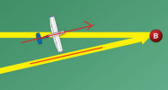
The wind calculation is just a vector sum operation. Airplane vector + wind vector = resultant vector. That's what the diagram is showing. The math becomes a lot simpler when drawn like this.
I would have put the wind arrow at the head of the orange arrow to make it conceptually a bit easier. But that doesn't change the result.
 
I would have put the wind arrow at the head of the orange arrow to make it conceptually a bit easier. But that doesn't change the result.
I suspect that the reason they did it the way they did is that course and wind are known, and heading, denoted by the orange arrow, is the unknown that you’re trying to find.
 
True, but you’ve got to drawl the other two before you can draw the HDG/TAS line.
This is why I think @Clip4 and @sarangan can't do what they say. The only way I know to draw a wind triangle is how I explained, at least if using just a protractor and ruler. To your point, though, the instant you can find your heading you can also find the groundspeed. Which one you measure first is up to you.

See figs 15 and 16: Path of Flight: Practical Information About Navigation of Private Aircraft
 
Last edited:
The wind calculation is just a vector sum operation. Airplane vector + wind vector = resultant vector. That's what the diagram is showing. The math becomes a lot simpler when drawn like this.
I would have put the wind arrow at the head of the orange arrow to make it conceptually a bit easier. But that doesn't change the result.
Which is all the wind side of your E6B is doing. Essentially, the wheel center and the mark are one vector that you are moving on top of the plane's airspeed/direction vector to find the resultant.
With a calculator and the law of cosines, you can calculate it as well
 
A maneuvering board (mo board as we called it) is a polar coordinate plotting sheet we used as ship drivers to solve relative motion questions.
Wipe that black shoe language out of your mouth! :D

Although I kept a similar one to reverse navigate where the ship should be when we were doing EMCON work and the E-2 wasn't there to help.
 
Yep. Classic boat thing! Giant kneeboard moboard!

And, uh, sorry about the black shoe thing, that was uncalled for… sorry!
 

Attachments

  • IMG_8007.png
    IMG_8007.png
    2.3 MB · Views: 15
This is why I think @Clip4 and @sarangan can't do what they say. The only way I know to draw a wind triangle is how I explained, at least if using just a protractor and ruler. To your point, though, the instant you can find your heading you can also find the groundspeed. Which one you measure first is up to you.

See figs 15 and 16: Path of Flight: Practical Information About Navigation of Private Aircraft
Isn’t a course plotter a protractor and a ruler? Actually you can draw it on a chart using the compass rose of a VOR and the mileage scale on the sectional by simply changing courses and winds to magnetic.
 
Back
Top