OK, here is the deal. I went back and found an obscure footnote to a design note that I got back in the late 1960s that said that a popular style of antenna splitter ("Wilkinson splitter", google at your peril) was good not only at the frequency for which it was designed, but at 3x the frequency, 5x the frequency and so on for all odd multiples of the frequency.
That led me to think that if we design a good splitter down at 343 MHz. it will also be good at our center frequency of 1035 MHz. I don't know that this is true, but I see no reason that it should NOT be true. Designing down at 300 MHz. is a deuce of a lot easier than at 1 GHz.
I know for a fact that this splitter design is VERY wide band; I've used it for YEARS down at the VHF nav band to split the VOR/LOC signal (108-118 MHz.) to two nav receivers and have tested it for equal split and "isolation" from about 80 MHz. to 150 MHz. and it is still "good" (a subjective term).
"Isolation" means that if you do something at one of the receiver ports, how much does that affect the other receiver port? The answer (once again subjective) is that you can short the #1 receiver port, you can open the #1 receiver port, and any combination in between and have VERY LITTLE effect on what happens at the #2 port.
And, the center frequency of the splitter is dependent on one thing and one thing only ... the lengths of two pieces of coax.
So, here is the deal. I will supply ONE of you with the parts to build said splitter. Free. You have to assure me that you have worked with RF and VHF at least (microwave preferred) and that you understand that a quarter of an inch difference or long leads more than a few tenths of an inch long will completely cob up the circuit. You have to be comfy with me being a real prick about construction techniques that I lay out.
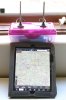
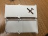
Having said all that, somebody volunteer and I'll give you my mailing address by email so that you can send me a self-addressed stamped envelope. What you will get back is coax cable, BNC connectors, a piece of PC board for construction and some rather detailed instructions. What I want back and posted on this group are pictures of what you made and subjective comments on how well it worked.
Once we prove that it worked and worked well, we can then proceed to making it smaller and easier to construct. But the breadboard has to be full-size without any shortcuts to prove the basic point.
Any takers?
Jim
") ...
...