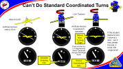
The chart is from a presentation I give on the original Link Trainer. They were fascinating devices...analog computers using vacuum as a "working fluid." When you climb, air is sucked out of a tank. Do a level turn, and small valves ooze a bit of vacuum out of the tank to show the loss of altitude unless you apply back pressure. Airspeed is "stored" in a vacuum manifold; dive the airplane and more vacuum is applied. The electronics on the device are basically there to translate the various pressures to needle positions on the gauges.
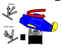
The vacuum in the airspeed manifold holds a flapper valve shut. If the airspeed (vacuum) gets too low, the flapper valve opens and the Link is "stalled".... vacuum is drained out of the altitude tank to make the Link "descend." At the same time, there's a left-and-right valve that flips over and puts the Link into a spin.
Oh, and because the stall valve would close if the Link is pitched down, the Link spins nose-high....
View attachment 139427
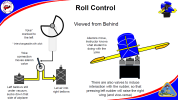
The aircraft attitude was set by (what else?) vacuum bellows. Four for roll and pitch, with vacuum sucking down full when in level flight. Roll the wheel to the left, and the right-side bellows gets a little less vacuum.
View attachment 139426
I doubt a modern engineering student could re-create it.
Ron Wanttaja