Nathan Miller
Pre-takeoff checklist
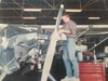
So, nearing the end of my avionics upgrades in my 172. (Self install under my IA's supervision. Posting to the group since she charges me $100 an hour  )
)

Still have a few misc things to take care of, as you can see.
But, today's conundrum: I've tracked down a static leak to, of all places, my static port! This took probably a day and a half to go through and eliminate small leaks here and there.
(Some back story- During the course of my G5 HSI install, I installed new 1/4" nylon hoses and fittings. My IA recommended I use a manifold style installation rather than the traditional/cheaper convention of putting a Tee behind each instrument and jumping from instrument to instrument.)
Bottom line, I taped over my static port and connected my hand vacuum pump to the threaded elbow inside the plane, just on the other side of the port, and the thing doesn't even TRY to maintain a vacuum. So, I'm guessing there's a crack in the little static port somewhere I can't see. Anyway, I find this quite surprising. How common is this part to fail? Thoughts and advice is appreciated.
)Still have a few misc things to take care of, as you can see.
But, today's conundrum: I've tracked down a static leak to, of all places, my static port! This took probably a day and a half to go through and eliminate small leaks here and there.
(Some back story- During the course of my G5 HSI install, I installed new 1/4" nylon hoses and fittings. My IA recommended I use a manifold style installation rather than the traditional/cheaper convention of putting a Tee behind each instrument and jumping from instrument to instrument.)
Bottom line, I taped over my static port and connected my hand vacuum pump to the threaded elbow inside the plane, just on the other side of the port, and the thing doesn't even TRY to maintain a vacuum. So, I'm guessing there's a crack in the little static port somewhere I can't see. Anyway, I find this quite surprising. How common is this part to fail? Thoughts and advice is appreciated.