Tom-D
Taxi to Parking
- Joined
- Feb 23, 2005
- Messages
- 34,740
- Display Name
Display name:
Tom-D

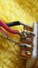
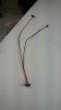
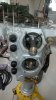
Well, here is your problem with who soldered it:
OOOOOOOOOUUUUUUUUUCCCCCCCCCCCHHHHHHHHHHHHHHHHHHHHHHHHHHHHHHHHHHHHHHH!!!!!!!!!!!!Well, here is your problem with who soldered it:


She is cold solderingWell, here is your problem with who soldered it:
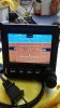
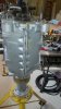
By the EFIS, my bench isn't level.
By the EFIS, my bench isn't level.
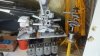
Yes If I use the instrument I'll make new harness.That is a stunningly bad solder job. Wow. And you say the whole harness is like that? Based on pictures of your earlier work, I assume you're redoing it all.
John
I cleaned up the primary DB -25 connector and installed the + & - wire just to see if the EFIS would light up. I will make new harness for it after the new connectors arrive. If I do sell it the buyer will get a good system.I hope that's a "before" picture. ;-)
Yes the installation manual is on line as to how to do that.that's how I found out which wires went where.Don't you have to calibrate it in the aircraft?
yes it is typical of the whole aircraft. The structure is great, but systems not so much.Hope that person didn't do any airframe or engine work!
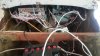
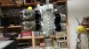
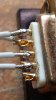
How does this look? more betta?Wow. That soldering job looks like something out of my Jr. High electronics class.
Worse, actually.
How does this look? more betta?
You want an honest answer? Those are incomplete solder joints, and you obviously didn't tin the wires first.How does this look? more betta?
I've replaced many cannon plugs like that, soldering every wire and re-soldered open connections in the center of the plug numerous times. Very tedious work.I worked at a place that gave me some soldering training. I figured I was already pretty good, but it was on a totally different scale.
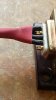
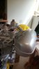
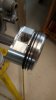
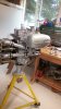
I remember soldering a cable onto the back of one of these:
I spent a long time getting it right and showed it to the inspector/trainer. She looked at it for a while and said, "That looks OK. Now give me three more."
How does this look? more betta?
You want an honest answer? Those are incomplete solder joints, and you obviously didn't tin the wires first.
Are those cobwebs crossing over between the pins? I see little hairs there.
But you appear to have busted them off or whatever when the shrinkydink was added/finished up.
How so? they positively were tinned. but I did touch pin with the iron that didn't need to be soldered.You want an honest answer? Those are incomplete solder joints, and you obviously didn't tin the wires first.
How so? they positively were tinned. but I did touch pin with the iron that didn't need to be soldered.