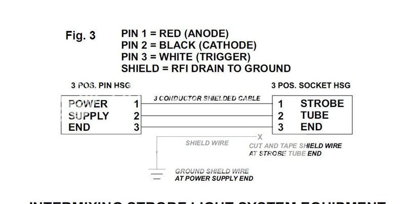
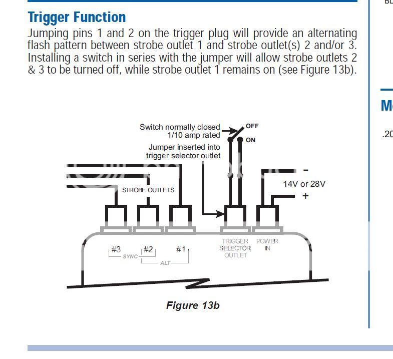
Strobe power supply function

flyingcheesehead

Touchdown! Greaser!
Joined
Feb 23, 2005
Messages
24,256
Location
UQACY, WI
Display Name

Display name:
iMooniac
Hi all,

I have a dead tail strobe. The tube has been replaced, still not working.

It's relatively easy to access the power supply, so I got out the multimeter. Power is making it to the supply, and I'm getting high voltage (525ish) on the anode/cathode pins on the output. However, it appears that I'm getting nothing on the Trigger.

What sort of signal comes from the Trigger pin? I'm guessing it's normally zero, with a square pulse of some length every so often? What voltage would that pulse be, and would it be possible to see it on an average digital multimeter? I was showing zero VAC, so I switched to DC figuring that at least I would see it fluctuating, but I would imagine that if the pulse is a low enough voltage and/or short enough time that the multimeter could be faked out.

Thanks in advance for any tips!
 
Others may know more but I suspect it is a substantial pulse(many volts) but very short (like microseconds). Your DVM won't see it. Get a scope or something.
 
Not sure what the trigger voltage should be, but, the trigger pulse causes the xenon gas to ionize, which allows the high voltage to conduct, resulting in the high intensity flash of the flash tube.
 
Did you try plugging the wing strobes into the tail strobe's port on the power supply?
 
Did you try plugging the wing strobes into the tail strobe's port on the power supply?

I thought about that, but before I took it apart I looked at the pics of the insides of my wingtips to be sure it'd work, and the connector is all the way inside the wing, the wires are crimped in the tip. Grrrr. :( (EDIT: I suppose I should explain here that my system has separate power supplies for each strobe, not merely three ports on one supply.)

So, I'll probably do the opposite and remove one of the wingtip power supplies and connect it to the wiring for the tail strobe as I won't have to cut anything then. But, that's a lot of screws to remove if someone can simply tell me that the 0VAC/0VDC I saw on the trigger indicates a failed supply. :) Plus, of course, I'm curious!
 
Hi all,

I have a dead tail strobe. The tube has been replaced, still not working.

It's relatively easy to access the power supply, so I got out the multimeter. Power is making it to the supply, and I'm getting high voltage (525ish) on the anode/cathode pins on the output. However, it appears that I'm getting nothing on the Trigger.

What sort of signal comes from the Trigger pin? I'm guessing it's normally zero, with a square pulse of some length every so often? What voltage would that pulse be, and would it be possible to see it on an average digital multimeter? I was showing zero VAC, so I switched to DC figuring that at least I would see it fluctuating, but I would imagine that if the pulse is a low enough voltage and/or short enough time that the multimeter could be faked out.

Thanks in advance for any tips!

I pretty well beat that subject to death in a series (Jul-Aug) in Kitplanes 2007. Here is the last in that series which pretty well sums up all three issues. If you want all three, let me know and I'll post them here.

By the way, if anybody should ask, this new board format is HORRIBLE.

Thanks,

Jim
 

Attachments

  • KP0709-small.zip
    26.6 KB · Views: 25
[QUOTE="weirdjim, post: By the way, if anybody should ask, this new board format is HORRIBLE
Ji[/QUOTE]I thought it was maybe just my eyes but I agree!
 
He only said he had voltage, many electrical problems are simply a loss of ground or loose connection. Oh please your self.

Kind of difficult to get the high voltage supply without a ground now, isn't it? He didn't ask how to troubleshoot the supply, just what the trigger pulse looks like. Why not simply ATFQ?

Please.

Jim
 
IIRC, the strobe tube gets around 1000 volts and the trigger about 4000. I'd bet that the power supply is dead.

BTW, did you check the supply voltage at the supply input with it connected? A poor connection or oxidized switch or breaker can drop the amperage, but the voltage will look OK at the supply if there's no load on it. No current flow, no voltage drop.
 
Kind of difficult to get the high voltage supply without a ground now, isn't it? He didn't ask how to troubleshoot the supply, just what the trigger pulse looks like. Why not simply ATFQ?

Please.

Jim
YTFE,WDYATQ? Uh, you supply the meter with its own ground when checking voltage. SEYA!
 
[QUOTE="GlennAB1, post: 2028109, member: 26616 Uh, you supply the meter with its own ground when checking voltage. SEYA![/QUOTE]

Perhaps you do, but not if you know what in the hell you are doing when troubleshooting. CUL es QSL. Please.

Jim
 
The aircraft I work on have a current path return (ground) maximum DC resistance of 2.5 milliohm. Good luck checking that with a standard multimeter/ohmmeter set on volts
 
Last edited:
And I'm supposed to be impressed? It WOULD have impressed me if you had taken the time to figure out that it was in all probability a CesBeePipooney of some sort with a "hefty" (for a light single) 60 amp alternator. As a matter of fact, from the dim photo in his avatar it looks like one of the Piper indian series. Even so, using the standard maximum of 60% of load, he can pull 36 amps with everything on. If we accept your standard of 2.5e-3 ohms then the maximum voltage loss would be 90 millivolts, which to a 12 volt system that can vary +/- 1000 millivolts around the bogey value of 13.6 volts isn't a fart in a whirlwind. Wanna try again?

Just for grins and giggles, tell me what he would feel when he touched the case of the power supply if it were NOT grounded and the high voltage was indeed 500+ volts relative to airframe ground. Want me to draw you a picture?

Oh, and yeah, I've been through 707/727/737, DC-9/MD80, and L-188 schools and understand the airline standards, probably as well as you. I also understand the real world of light singles VERY well.

NOw let's stop this bushwa and get back to solving HIS problem, not your cardboard airline's problems.

The aircraft I work on have a current path return (ground) maximum DC resistance of 2.5 milliohm. Good luck checking that with a standard multimeter/ohmmeter set on volts

Actually pretty trivial. Most digital voltmeters (even the Harbor Freight variety) have a full scale reading of 200 millivolts. Most of us have a 1 ohm resistor laying around for just the purpose. Run the 12 volt battery into the 1 ohm resistor (12 amps, remember Ohm's derivative law? and measure the voltage drop from the negative lead of the battery (directly) to the airframe where the resistor is "grounded". From R=E/I (another derivative) the voltage drop for the stated current is by definition the return resistance (factoring in the known long lead from the negative terminal to the voltmeter and the positive terminal to the resistor). Not rocket science, not even high school algebra science.


Jim
 
That's good Jim, why haven't you fixed it yet? I wouldn't expect the max allowable voltage drop to equate to a fart in the wind, that's why it's allowable. Show of hands if you have a 1 ohm resistor laying around.... uhhhh, nobody.... but, you and I.
 
Last edited:
I probably do. I'd have to look...
 
The "us" refers to wrenchbenders that do this stuff for a living. More specifically sparkie wrenchbenders. By the way, the "battery load testers" from Harbor Freight make a pretty nice and cheap low-ohm resistor for such a test. Of course, it isn't traceable to NBS standards so I wouldn't DARE use it for a part 121 test. Just like we didn't have 55 gallon barrels of Marvel Oil in the corner of the hangar back in the DC-6 and -7 days that were covered by a shop blanket when the FAA came around for an inspection. No sireee, not us, no way.

Why haven't I fixed it? He asked what the trigger signal was like, and I sent him an article and a schematic explaining it exactly. What else do you expect me to do, telepathy repair?

Jim
 
Last edited:
Hi all,

I have a dead tail strobe. The tube has been replaced, still not working.

Just FYI, that flashtube has a red dot on one end that is supposed to be connected to the positive power supply. I don't quite understand how a symmetric flashtube can have a polarity, but I'm sure that the manufacturer has a reason to specify the polarity.

Be cautious around that sucker. Here is a good reference if you need more reading:
donklipstein.com/donflash.html
shok.jpg


jw
 
Last edited:
I pretty well beat that subject to death in a series (Jul-Aug) in Kitplanes 2007. Here is the last in that series which pretty well sums up all three issues. If you want all three, let me know and I'll post them here.

Great info, Jim, thanks! I would love to see the other two as well.
 
That's good Jim, why haven't you fixed it yet? I wouldn't expect the max allowable voltage drop to equate to a fart in the wind, that's why it's allowable. Show of hands if you have a 1 ohm resistor laying around.... uhhhh, nobody.... but, you and I.
Another hand, plus many K's and Megs, along with a couple hundred assorted ICs, transistors, and too many different caps to count.
 
Hi all,

I have a dead tail strobe. The tube has been replaced, still not working.

It's relatively easy to access the power supply, so I got out the multimeter. Power is making it to the supply, and I'm getting high voltage (525ish) on the anode/cathode pins on the output. However, it appears that I'm getting nothing on the Trigger.

What sort of signal comes from the Trigger pin? I'm guessing it's normally zero, with a square pulse of some length every so often? What voltage would that pulse be, and would it be possible to see it on an average digital multimeter? I was showing zero VAC, so I switched to DC figuring that at least I would see it fluctuating, but I would imagine that if the pulse is a low enough voltage and/or short enough time that the multimeter could be faked out.

Thanks in advance for any tips!
Too bad you didn't take readings from one that was working, we wouldnt be here.
 
Last edited:
Maybe I am mis-reading the question here, but let me take a stab. I read your update with the two power supplies as well, but not 100% positive on how they are wired on your plane.

If this is a Whelen power supply with a trigger connector, you should not meter any voltage off of the output of the trigger connector. The purpose of this connector is to allow discreet control of output #1 (normally tail strobe) and the other connectors. The power supply will activate the strobe plugged into output #1 when there is voltage going into the power connector. Once the terminals on the trigger port are connected by contact closure, the remaining outputs will be activated. In most configurations, output #1 goes to the tail and is powered first and the trigger wire goes to a switch on the panel that provides a closure to turn on the wingtip strobes.

For your troubleshooting, I would just make sure that there is a looped connector bridging the pins of the trigger port to ensure that all outputs are active. As others have suggested, plugging the tail strobe wire into a known-good power supply output should help to narrow down the issue to wiring, flash tube, or power supply. Good luck.
 
Too bad you didn't take readings from one that was working, we wouldnt be here.

Well, it was February and I'm in Wisconsin and I'm in an unheated hangar! :eek:

I think I know which panel the wingtip supply is under, once I have it open I should be able to plug that into the tail power and tube pretty easily. I was hoping the wingtip tube had the same molex connector in an accessible spot so I could switch tubes instead of power supplies, but no such luck. In fact, on the wingtips, the power supply is probably easier to get out than the tube.
 
Maybe I am mis-reading the question here, but let me take a stab. I read your update with the two power supplies as well, but not 100% positive on how they are wired on your plane.

If this is a Whelen power supply with a trigger connector, you should not meter any voltage off of the output of the trigger connector. The purpose of this connector is to allow discreet control of output #1 (normally tail strobe) and the other connectors. The power supply will activate the strobe plugged into output #1 when there is voltage going into the power connector. Once the terminals on the trigger port are connected by contact closure, the remaining outputs will be activated. In most configurations, output #1 goes to the tail and is powered first and the trigger wire goes to a switch on the panel that provides a closure to turn on the wingtip strobes.

For your troubleshooting, I would just make sure that there is a looped connector bridging the pins of the trigger port to ensure that all outputs are active. As others have suggested, plugging the tail strobe wire into a known-good power supply output should help to narrow down the issue to wiring, flash tube, or power supply. Good luck.

Try not to make it more confusing... Whelen should have called the flash pattern selector something other than "trigger" since every strobe supply has a high voltage flash tube trigger circuit.


Last edited:
Maybe I am mis-reading the question here, but let me take a stab. I read your update with the two power supplies as well, but not 100% positive on how they are wired on your plane.

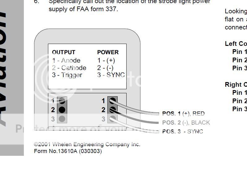
I think it's actually three power supplies. The one in question, the tail supply, has two molex connectors with the following:

1) Power: +, -, Sync
2) Output: Anode, Cathode, Trigger.

The Power connector does have +25VDC across the + and - terminals (engine off). With the power connector attached, I was seeing over 500VDC across the Anode and Cathode, but nothing on the trigger when the multimeter was set to either AC or DC.

Based on the difference between what you're describing and what I have I think the system you're describing is a bit different - I don't have multiple pins on a "trigger port", there's just the one trigger pin on the Output port.

If this is a Whelen power supply with a trigger connector, you should not meter any voltage off of the output of the trigger connector. The purpose of this connector is to allow discreet control of output #1 (normally tail strobe) and the other connectors. The power supply will activate the strobe plugged into output #1 when there is voltage going into the power connector. Once the terminals on the trigger port are connected by contact closure, the remaining outputs will be activated. In most configurations, output #1 goes to the tail and is powered first and the trigger wire goes to a switch on the panel that provides a closure to turn on the wingtip strobes.

For your troubleshooting, I would just make sure that there is a looped connector bridging the pins of the trigger port to ensure that all outputs are active. As others have suggested, plugging the tail strobe wire into a known-good power supply output should help to narrow down the issue to wiring, flash tube, or power supply. Good luck.
 
Time out. TIME OUT. TIME TIME TIME TIME OUT. If the sucker worked at one time, and if nobody diddled with the connections to the power supply, then checking to see if this and that are jumpered and that and this are connected correctly are only going to confuse the issue. Messing around changing around stuff that wasn't broken in the first place is a SURE WAY to honk up the troubleshooting process. I really and truly DO HOPE you didn't start fiddling with the connections on the once-working power supply. You only need two things to make that tube fire. One is a constant 500 (+/-) volts across the tube and a few microsecond 4000 volt (+/-) volt trigger pulse at the trigger terminal of the tube. If both of those are present, then you've got a tube problem. If they are NOT, then you've got an electronic problem. PLEASE don't honk up the installation that once worked.

Thanks,

Jim
 
Time out. TIME OUT. TIME TIME TIME TIME OUT. If the sucker worked at one time, and if nobody diddled with the connections to the power supply, then checking to see if this and that are jumpered and that and this are connected correctly are only going to confuse the issue. Messing around changing around stuff that wasn't broken in the first place is a SURE WAY to honk up the troubleshooting process. I really and truly DO HOPE you didn't start fiddling with the connections on the once-working power supply. You only need two things to make that tube fire. One is a constant 500 (+/-) volts across the tube and a few microsecond 4000 volt (+/-) volt trigger pulse at the trigger terminal of the tube. If both of those are present, then you've got a tube problem. If they are NOT, then you've got an electronic problem. PLEASE don't honk up the installation that once worked.

Jim,

I have not and will not do anything to any of the power supplies internally... No jumpering or diddling.

I've already replaced the tube, the new one does not work either. Since I have a 3-supply system, I should be able to simply remove a wingtip supply, plug in the power and output connections from the tail into the wingtip supply (after verifying that they're pin-compatible), and see if the tail strobe fires with the wingtip supply. If so, I'll simply buy a new power supply for the tail and be done with it.

OK, I may take apart the old supply afterwards, once I learn enough about safety of the HV parts to do so. :) But once I mess with it at that level it'll never go back in an airplane.
 
Jim,

OK, I may take apart the old supply afterwards, once I learn enough about safety of the HV parts to do so. :) But once I mess with it at that level it'll never go back in an airplane.

Two things will hurt you. The 500 volt main supply can easily kill you. The 4000-5000 volt trigger pulse may get your attention but the energy is low enough that it will probably (repeat PROBABLY) not do anything more than make you say "$#!+ that hurt"
 
Jim,
What's a little on-the-job training? Getting poked by one of those is a lesson you don't forget. ;)
 
Two things will hurt you. The 500 volt main supply can easily kill you. The 4000-5000 volt trigger pulse may get your attention but the energy is low enough that it will probably (repeat PROBABLY) not do anything more than make you say "$#!+ that hurt"

Always liked this warning sign...

ImageUploadedByTapatalk1457759533.060596.jpg
 
A capacitive discharge ignition system (ala Mercury outboard of the sixties) will really get your attention if you're standing n the water. DAMN! That hurt for a week.
 
A capacitive discharge ignition system (ala Mercury outboard of the sixties) will really get your attention if you're standing n the water. DAMN! That hurt for a week.

To boot, if you are standing in water up to your waist, the discharge is from the sharpest point on the structure, which on a human male is NOT the little toe.

Jim
 
To boot, if you are standing in water up to your waist, the discharge is from the sharpest point on the structure, which on a human male is NOT the little toe.

ROFLMAO... what we really want to know is how you KNOW that. :)
 
Back
Top