Sharing a breaker

Ed Haywood

Final Approach
Joined
Jul 12, 2020
Messages
7,624
Location
Tampa FL
Display Name
Ed
Home Airfield
FD77
I want to add a second AV-30. STC instructions say to install each device on a separate 2A breaker. I do not have physical room to add another breaker to the bus.

What are the basics of sharing two devices on a breaker? Is it as simple as picking a wire large enough to carry the load over the distance, and a breaker small enough to protect it, just like a single device? Is it best practice to run separate lines from the breaker for each device, or share a line and split at the device end? If the breaker is larger than 2A, do I need to install an inline fuse on each device to comply with the STC?
 
What are the basics of sharing two devices on a breaker?
Technically none. In general, circuit protection protects the wire and not the device. However, there are various ways to expand your existing power buss to make room for a separate CB for the 2nd AV30.
 
I have no idea what the power requirements of an AV-30 are, but I can think of a few good reasons they'd specify separate breakers, including that two devices might overload one breaker, and redundancy in case a breaker fails or one device fails and trips the breaker. As far as safety goes, at a minimum, you shouldn't increase the breaker size without a corresponding increase in the wire size.
 
Technically none. In general, circuit protection protects the wire and not the device. However, there are various ways to expand your existing power buss to make room for a separate CB for the 2nd AV30.

There is already a lot going on in a very small space in the breaker box. TBH, If I could splice a Y on the end of the run and bump up the breaker to 3A or 4A, I would rather just take the easy path here. Wire is 20ga shielded with 6 foot run.
 
Two AV-30s on a single breaker exposes you to a potential wiring fault that would end up with both losing power. I wouldn't do it.

Instead, if you really can't find a place for a second breaker, double the value of the breaker and follow it with two 2A in-line PTC self-resetting fuses, one for each AV-30. I can help you with some suitable part numbers if you need it. That way you still have a CB to easily remove power from both, if needed, but any fault with one of them (or the wiring) won't take the other one out.
 
Last edited:
Be sure to pick a device that if failed at the same time due to breaker trip, will not leave you without proper redundancy.

Obviously not the other AV-30
 
There is already a lot going on in a very small space in the breaker box. TBH, If I could splice a Y on the end of the run and bump up the breaker to 3A or 4A, I would rather just take the easy path here. Wire is 20ga shielded with 6 foot run.
What will be the purpose of the 2nd AV-30?

Do you have a separate avionics master switch?

Do you have a representative wire diagram for your aircraft you can post?

When you were refurbing this aircraft, did you post on PoA any pics of your panel, electrical, etc?
 
What will be the purpose of the 2nd AV-30?
Non required safety enhancing equipment. Aircraft is legally VFR only. First AV-30 is AI. Second AV-30 will display DG/HSI/traffic for XC nav convenience and better usability in case of an inadvertent entry into IMC.

First AV-30 was installed under STC. In theory I could uninstall and reinstall under NORSEE using methods in AC 43.13-1B, no?
Do you have a separate avionics master switch?
Yes
Do you have a representative wire diagram for your aircraft you can post?
Attached
When you were refurbing this aircraft, did you post on PoA any pics of your panel, electrical, etc?
Yes
 

Attachments

  • ACA elec - bus.jpg
    ACA elec - bus.jpg
    285.1 KB · Views: 14
Last edited:
Why not simply add the new AV-30's load to another less critical breaker, like the TC? You may need to up the breaker capacity.
 
Share a photo of your CB’s and someone can suggest a reroute.
 
Why not simply add the new AV-30's load to another less critical breaker, like the TC? You may need to up the breaker capacity.
I do have a few options there. Engine monitor is non-primary and on it's own breaker. USB charger is on a breaker, though I am probably going to have to add another of those too.

A few primary engine gauges (OT, OP, and FP) are on a breaker. They draw very little current, like tenths of an amp. But would probably be smart to keep that on its own circuit.

Engine monitor and USB charger are on avionics bus. Gauges are on main bus.
 
First AV-30 was installed under STC. In theory I could uninstall and reinstall under NORSEE using methods in AC 43.13-1B, no?
Not really. NORSEE policy has its own requirements which are spelled out in the policy statement. However, I am assuming since you will be displaying DG/HSI/traffic on the 2nd AV you will still be using the STC installation instructions to accomplish this?

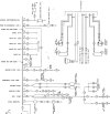
Label what specific device is connected to your avionics buss by wire number (128, 129, etc) per the diagram below.

Verify the 2nd bus bar break between wire 22 and 23 is there.

Verify wire 375 is installed.

Post pic(s) of panel where 2nd AV-30 will be installed.

Post pic of electrical panel with CBs. Is it still located at upper LH side of cockpit?

If possible, post pic of where wire 315 connects to bus bar and where wire 375 connects to bus bar at wire 22.

1745938432894.png
 
I deviated from this diagram. The original TC drawings did not have an avionics master. When the factory modified the spec, they took the most expedient path to modify the existing fleet, which was to cut the bus in two places.

Since I was building a bus from scratch, I reordered the breakers so the avionics were on the last 4 stations. Thus my bus only has one break, and no wire 375.

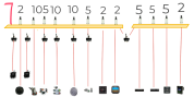
Here is my current configuration. Device icons across bottom are mag, stall warning, mag, fuel pump, master solenoid, strobes, nav lights, landing light, engine gauges, AV-30, radio, transponder, USB port, and engine monitor. I later moved the avionics switch left, between the master and the strobe switches.

Screenshot_20250429-112907.png
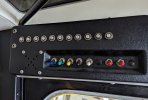
I could remove the cockpit speaker from the panel. That would open up space for 2 or 3 breakers. Older models housed the speaker in a separate box on the other side of the cockpit, and I do still have that box, but I would probably need to source a new breaker panel shell.

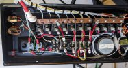
Here are pictures of the panel box before I labeled it.

PXL_20231115_195627661~2.jpg

PXL_20230215_212917957~2.jpg

It looks like there is room to move the bus left one station, but it won't work. There is a frame member where it mounts that gets in the way. Believe me, I tried.
 
Last edited:
However, I am assuming since you will be displaying DG/HSI/traffic on the 2nd AV you will still be using the STC installation instructions to accomplish this?

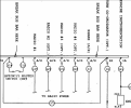
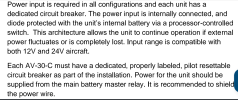
Yes I was planning on it, unless there was another path that was equally easy. That's the main obstacle. The STC references the MDL. The MDL references the installation manual. The installation manual is unambiguous, and would seem to preclude an inline fuse:

Screenshot_20250429-131634.png
 
Here is my current configuration. Device icons across bottom are mag, stall warning, mag, fuel pump, master solenoid, strobes, nav lights, landing light, engine gauges, AV-30, radio, transponder, USB port, and engine monitor. I later moved the avionics switch left, between the master and the strobe switches.
The easiest route would be to replace the USB charger CB with a 2A, connect your 2nd AV there, then add a 5A inline fuse for the USB device and connect it to a convenient bus bar screw. Should be able to accomplish that with the existing wire runs. And be able to follow the STC.
 
The easiest route would be to replace the USB charger CB with a 2A, connect your 2nd AV there, then add a 5A inline fuse for the USB device and connect it to a convenient bus bar screw. Should be able to accomplish that with the existing wire runs. And be able to follow the STC.
Awesome, thanks!

As an alternative, if I do get rid of the speaker, could I mount another breaker there and jumper it off the main or avionics bus bar?

Inline fuse would be as close as possible to the bus bar, correct?
 
Question about the jumper, what's the best practice for determining what gauge wire to use, also is there a limit on how many breakers are being used?
For just a jumper, its either sized for the combined electrical load of all systems that you are jumping to or if a single system/load the same size wire of that system. Regardless, the starting point is always from a known wire sizing reference like AC 43.13-1B Chap 11. The main limiting factor on the number of breakers, especially if adding more circuits, is that the total electrical load cannot exceed 80% of the electrical system rating.
 
Notice the word DEDICATED. That means NOT SHARED with anything.
 
Well, so many people were suggesting to share a breaker. So not quite that obvious.
 
Back
Top