On obtaining approved data for Avionics installs

Tom Cipollone

Filing Flight Plan
Joined
Sep 19, 2017
Messages
3
Display Name

Display name:
miner_tom
Hi, this is my first post on this forum.

I am an A&P student who has spent many years (decades) as an electronics engineer. I wish to be able to service my own plane.

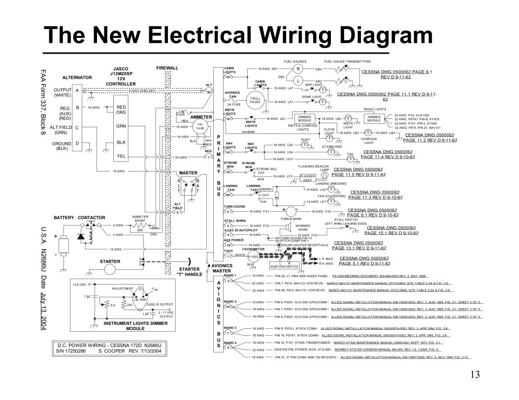
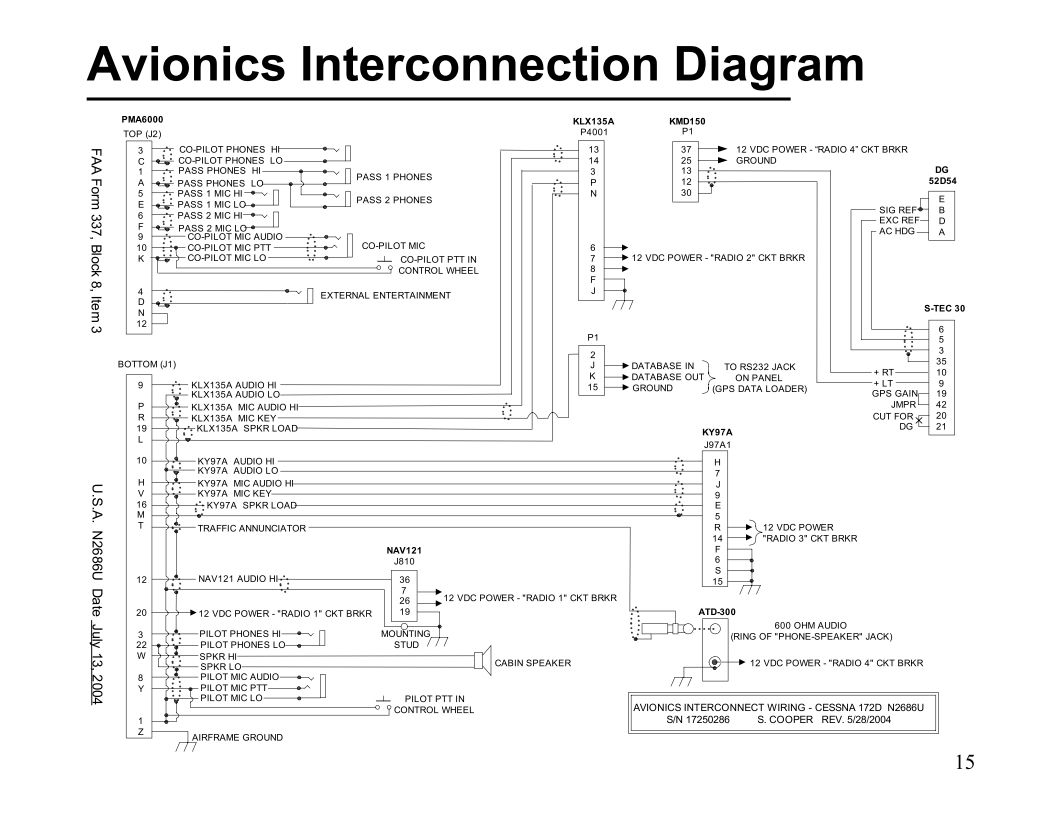
I was doing work at a 145 repair station during the summer doing cable harnesses and "installs". One thing that I saw was that the repair station had mountains of documentation from the manufacturers of various controls, radios and indicators. Working with this documentation I realized that there are certain "approved" indicators, lets say, that will work with certain radios. The manufacturer of the radio will provide the necessary interface information to the indicators.

In a hypothetical case, lets say that I have a set of indicators in my plane and I wish to install a new radio. I would have to obtain the documentation for that radio where the interface schematic would be shown, in order to create the proper wiring harness and pinouts for the connectors. I was told that this information had to come in print or hard copy form from the manufacturer and not be downloaded from the internet (where it would not be considered approved data).

How true is the above statement? How does the "home-brewed" avionics technician get approved data? Can the data be downloaded if it is available?

Thank You
Tom
 
Tom, when I upgraded the avionics stack and electrical system (D.C. generator with mech voltage regulator to alternator with solid state voltage controller) in my 172 with all new equipment in 2004, the local FSDO inspector wanted a complete wiring diagram and avionics interconnection diagram to be included with the 337, including reference to the installation manuals for all of the hardware. I believe this is fairly typical.

N2686U%20Project%200405%20Electrical%20Diagram_zpsqlrt0xpd.jpg


N2686U%20Project%200405%20Avionics%20Interconnection_zpsudoy7qsw.jpg

N2686UPanelJAN05small.jpg
 

First we all need to understand that a manufacturer's drawing or manual may very well NOT be FAA approved. "FAA approved" is the most abused term in all of aviation. (Something like an ELT installation manual contains FAA approved data but it is not an installation approval).

Typically a repair station or engineering firm collects all these different manuals and draws thier own set of prints that are specific for the aircraft alteration they wish to perform (or sell) and those documents are what actually get sent to a unit member or FAA to be approved.

You can use whatever you download from the net, what a dealer gives you etc, to create a data package that is approvable.
 
Last edited:
Tom, when I upgraded the avionics stack and electrical system (D.C. generator with mech voltage regulator to alternator with solid state voltage controller) in my 172 with all new equipment in 2004, the local FSDO inspector wanted a complete wiring diagram and avionics interconnection diagram to be included with the 337, including reference to the installation manuals for all of the hardware. I believe this is fairly typical.


That level of detail is very lacking in the small aircraft world and it is kinda sad. Your work is an example of what is expected in the real world. Everytime you leave a shop that mods wiring you really should be getting prints.
 
First, assuming what you're doing is a minor alteration, you don't need "approved" data; you only need "acceptable data." If you need "approved" data for an major alteration, you get it via a STC (which likely incorporates the MFG install manuals) or by submitting a 337 to the FSDO (or now FSO) referencing the install manuals as "acceptable" data and having the inspector sign the 337, thereby creating "Approved" Data.

Also, beyond a company policy (or something contained in a binding repair station manual, which is a different animal entirely), you don't need hard copies of the manuals. Nothing in the regs render electronic copies unacceptable.
 
Last edited:
Major / minor determination is whole study by itself but is the first step, detrmining if you need approved data or acceptable data.
 
Tom, when I upgraded the avionics stack and electrical system (D.C. generator with mech voltage regulator to alternator with solid state voltage controller) in my 172 with all new equipment in 2004, the local FSDO inspector wanted a complete wiring diagram and avionics interconnection diagram to be included with the 337, including reference to the installation manuals for all of the hardware. I believe this is fairly typical.

N2686U%20Project%200405%20Electrical%20Diagram_zpsqlrt0xpd.jpg


N2686U%20Project%200405%20Avionics%20Interconnection_zpsudoy7qsw.jpg

N2686UPanelJAN05small.jpg
Thank you for your most thoughtful reply. I have some follow up questions.

I noticed that the drawing that you included here looked quite professional. I am assuming that since you were submitting your proposed changes to the FDSO, that you drew this diagram yourself. Since I am a EE, I have worked with many schematic capture programs for printed circuit boards but it looks as if you did your drawing with a wiring diagram program, such as "Solidworks Electrical". I do have it but I have not used it much. May I ask which program you used for the drawing. Possibly Autocad?

Included in the drawing proposal are many "tags" or "pointers" to specific documents pages from Cessna, etc. I am assuming that you downloaded these documents for you aircraft directly from the manufacturer, with the proper serial number for the aircraft, etc. My question is, how can you be sure that the FDSO will have access to the same documentation in order to check to see that the connections are correct? Did you have to provide those documents to the inspector and if so, how would they make the determination as to approved data or acceptable data? I am assuming that whoever is examining the proposal would check the connections, since an incorrect connection may or may not cause a safety issue (fire).

I am still trying to connect all of the dots.

Thank You
Tom
 
Tom, I used Microsoft Visio for the drawings. I purchased CD-ROMs of the Cessna parts and maintenance manuals from Cessna for the 1963 Cessna 172D models, including the serial number of my airplane. All the equipment I installed - with a couple of exceptions - was purchased new, and installation manuals were included. The Narco NAV 122 was purchased used, but reprints of the installation and service manuals were available from a vendor who widely advertised at the time, but I've forgotten the name. EDIT - The company that supplies manual reprints is ESSCO Aircraft. https://www.esscoaircraft.com/

The FSDO inspector arranged to meet me at my place of employment, and we scheduled a conference room where we could sit down and review the manuals and my hand drawn diagrams. He also frequently stopped by the airport to look at my progress on the project.

I made all of the interconnection cables on my dining room table and connected all the equipment including 50 ohm dummy loads on the transceivers and GPS antennas on the GPS receivers, and tested interoperability of all the equipment using a regulated and well filtered 25 amp 13.8 VDC power supply, before installing it in the airplane.

All the work on the airplane was done by me under the supervision of my A&P/IA.

A PowerPoint presentation (pdf) of the whole project is posted on pdf-archive.com HERE if you're interested.
 
Last edited:
Thank you for your most thoughtful reply. I have some follow up questions.


The FSDO does not require the manuals, mostly because they are only approving the equipment is appropriate for the airplane and responsibility for the installation and quality still falls on the installer. Also why its always gonna need a reference for ground testing the installation.

I also put together a full electrical load analysis including any needed data from the OEM aircraft's manuals.

A lot of equipment will come with an STC data package and more than likely no separate approval is needed.
 
Tom, I used Microsoft Visio for the drawings. I purchased CD-ROMs of the Cessna parts and maintenance manuals from Cessna for the 1963 Cessna 172D models, including the serial number of my airplane. All the equipment I installed - with a couple of exceptions - was purchased new, and installation manuals were included. The Narco NAV 122 was purchased used, but reprints of the installation and service manuals were available from a vendor who widely advertised at the time, but I've forgotten the name.

The FSDO inspector arranged to meet me at my place of employment, and we scheduled a conference room where we could sit down and review the manuals and my hand drawn diagrams. He also frequently stopped by the airport to look at my progress on the project.

I made all of the interconnection cables on my dining room table and connected all the equipment including 50 ohm dummy loads on the transceivers and GPS antennas on the GPS receivers, and tested interoperability of all the equipment using a regulated and well filtered 25 amp 13.8 VDC power supply, before installing it in the airplane.

All the work on the airplane was done by me under the supervision of my A&P/IA.

A PowerPoint presentation (pdf) of the whole project is posted on pdf-archive.com HERE if you're interested.


Stan, utterly fantastic! What you did follows good engineering procedure.

1) Research the components
2) Come up with a well documented plan (schematic)
3) Build and test
4) Confirm

Thank you for showing me how it is done.

Interesting, however, is your use of Microsoft Visio. I have used it in the past for things like presentations but I found it rather clunky WRT drawings. It was less versatile than a standard schematic capture program for drawing traces/wires. Must have been improved in the recent past.

Oh, and one final thing. I did attempt to download your presentation from the link that you posted but all that I could find were links to Asian "dating sites" and other soft porn. Can you provide another link?

Regards
Tom
 
Last edited:
Tom, thank you. Having an enthusiastic A&P and an FSDO inspector that went out of his way to provide guidance were both huge assets (the FSDO inspector's name is Dennis Thorpe, and he is now the head guy at the Oakland, CA FSDO).

Visio is clunky for producing schematics, but it was what I had available and I was familiar with it. This was thirteen years ago and I didn't want to take the time to learn a new software package.

The link works for me, but if you shoot me an email (k4drd<at>earthlink.net), I'll email you the pdf file (2 MB).
 
The FAA has published their policy in as much as a radio up grade is not a major alteration, unless the instrument panel is modified. or the weight and balance is modified to the extent it no longer meets the requirements of FAR 43-A. and in some cases where STCs are provided.
Contact your local FSDO for guidance. ask your A&P who their PMI is, that is the guy you need to talk to.
 
Back
Top