Does anyone know how to build and set up one of these AOE Glide slope visal aids? I haven't been able to find any technical information on them. Thanks in advance.
You are using an out of date browser. It may not display this or other websites correctly.
You should upgrade or use an alternative browser.
You should upgrade or use an alternative browser.
How to build alignment of elements glide slope aid?
- Thread starter William Pete Hodges
- Start date
I had some photos from the '70s showing how the boards were mounted on 4X4s, but I can't find them.
There is a Google maps view of the ones in North Dakota, but it is super low resolution and hard to make out the panels.
I'm sure there is a reference somewhere and I, too have been looking for one.
There is a Google maps view of the ones in North Dakota, but it is super low resolution and hard to make out the panels.
I'm sure there is a reference somewhere and I, too have been looking for one.
EdFred
Taxi to Parking
Yeah, put the 2 outside boards closer to the arrival end and higher than the middle one.
For each 20" closer to the arrival end the outside boards are compared to the center one, put the outside boards 1" higher for a 20:1 approach path.
For each 20" closer to the arrival end the outside boards are compared to the center one, put the outside boards 1" higher for a 20:1 approach path.
Well I suppose if you knew the target slope angle, and what the tolerances for high and low are
then it could be figured out with a little bit of trigonometry
the middle board is behind and lower than the side boards I recon... just simply based on the angles
the height of the boards would probably be depending on how wide the tolerance is from above to below.... for a nice sight picture....
but how big to make the boards and how far apart to space them to get a proper nice visual.... I don't know...maybe trial and error... would say 2ft x 4ft panels big enough? or maybe they need to be more like 2x6? I recon dependent on speed and distances in play....
EdFred
Taxi to Parking
Well I suppose if you knew the target slope angle, and what the tolerances for high and low are
then it could be figured out with a little bit of trigonometry
the middle board is behind and lower than the side boards I recon... just simply based on the angles
the height of the boards would probably be depending on how wide the tolerance is from above to below.... for a nice sight picture....
but how big to make the boards and how far apart to space them to get a proper nice visual.... I don't know...maybe trial and error... would say 2ft x 4ft panels big enough? or maybe they need to be more like 2x6? I recon dependent on speed and distances in play....
I'd want em 40' apart front to back and probably 20' outer edge to outer edge, and 2' height difference for a 20:1 and probably 30" x 60" each in size.
- Joined
- May 11, 2010
- Messages
- 20,558
- Location
- Charlotte, NC
- Display Name
Display name:
Snorting his way across the USA
I've never really thought about it before, but now I understand how those things work.
I have been working on the math for this and have made a couple of assumptions that I am not sure are right. If we want the base glide slope to be 3° with the boards aligned, and if we want 2.5° slope with the center board aligned underneath, and a 3.5° slope with the center board aligned on top, and if the boards are 16" tall and 32" wide, the the center board must be 152.8 feet behind the front two boards. That seems like a lot of distance to me but that seems to be the way the math works out.
Now if use 2°, 3°, and 4° then the center board would be 76.4 feet behind the front 2 boards. 16" ÷ (SIN 1°) = 916.78 ÷12 = 76.398 feet.
If we want a 3° base slope the the front boards need to be 4 feet above the rear board. 76.398 x SIN 3° = 3.998 feet. I know they have one of these at Shannon airport but I didn't think it took up that much space.
I might be looking at it wrong. It sure would be nice if there was a written text on this.
Last edited:
Daleandee
Final Approach
- Joined
- Mar 4, 2020
- Messages
- 6,753
- Display Name
Display name:
Dale Andee
Dunno if this helps. Found here: https://www.reddit.com/r/hoggit/comments/iqca3n/how_to_create_a_simple_glide_path_indicator_to/
I think that ours were 4X4 plywood, and mounted high enough to allow easy grass cutting around and under.
The design was with thin plywood, and relatively fragile supports to break away if hit by a plane. A serious wind storm wrecked the set at one end of the runway, but that is a tradeoff, they are cheap to replace.
We also had a short post with flood light on it for night use, tied into the runway lights, Pilot controlled.
Metric? Pshaw! Can you please convert the ratios to American?
Dunno if this helps. Found here: https://www.reddit.com/r/hoggit/comments/iqca3n/how_to_create_a_simple_glide_path_indicator_to/
")
Daleandee
Final Approach
- Joined
- Mar 4, 2020
- Messages
- 6,753
- Display Name
Display name:
Dale Andee

Let'sgoflying!
Touchdown! Greaser!
luvflyin
Touchdown! Greaser!
Wood, saw, hammer, nails, paint and trigonometry. If you don't know trig, there's always trial error. Be carefulView attachment 108086
Does anyone know how to build and set up one of these AOE Glide slope visal aids? I haven't been able to find any technical information on them. Thanks in advance.
Dunno if this helps. Found here: https://www.reddit.com/r/hoggit/comments/iqca3n/how_to_create_a_simple_glide_path_indicator_to/
I am not installing the Reddit App to look at that, so I can't see the whole article. 1 meter is 3.28084 feet, so 300 meters is 984.25 feet. 30 meters is 98.425 feet, 10 meters is 32.81 feet, and 76 meters is 249.344 feet.
Placing the boards about 1000 feet from the end of the runway sounds like a lot of distance on a small runway of say 2000 feet total. But 300 feet from the end sounds about right. If you figure the dimensions are in feet instead of meters, then 76 feet is pretty close to my calculated 76.4 feet.
That tells me I am on the right track anyway. One Miracle at a time!
Every airport in Maryland had these at one point. I call them the "plywood approach path indicator" but apparently that acronym has already been used .
A few years ago, a military portable VASI showed up at the consignment tent at Oshkosh. It was decided that I needed to have one. I've got it operational with two spare bulbs, but I don't know how well it works in the daytime. We've been meaning to set it up and test, but the place that makes the most sense for its location is at the airport bar and by the time we've had a few Coronas or Margeritas, nobody is in the shape to fly to test it.
.A few years ago, a military portable VASI showed up at the consignment tent at Oshkosh. It was decided that I needed to have one. I've got it operational with two spare bulbs, but I don't know how well it works in the daytime. We've been meaning to set it up and test, but the place that makes the most sense for its location is at the airport bar and by the time we've had a few Coronas or Margeritas, nobody is in the shape to fly to test it.
EdFred
Taxi to Parking
The trigonometry is easy, but for day VFR why is this needed?
Of course if I was flying a 20:1 approach path I'd be so far below my plane's glide angle I'd be real nervous.
Then you aren't flying the FAA "mandated" stable approach!
MauleSkinner
Touchdown! Greaser!
So you can tell if the trees have grown into the protected area.The trigonometry is easy, but for day VFR why is this needed?
Of course if I was flying a 20:1 approach path I'd be so far below my plane's glide angle I'd be real nervous.
Zeldman
Touchdown! Greaser!
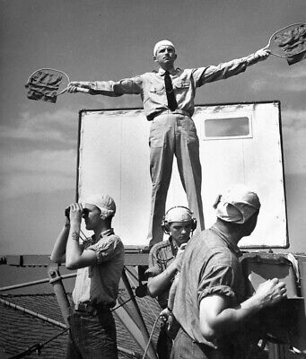
I understand these guys are looking fer work....
The panels I remember from a small airport in Northern California were 4X8 plywood sheets.
The two panels in the front were up on 4X4 posts about maybe six feet. I have seen bigger versions and yes, they were very visible in daylight and also lighted at night.
The two panels in the front were up on 4X4 posts about maybe six feet. I have seen bigger versions and yes, they were very visible in daylight and also lighted at night.
nice! I sure would like to fly an approach or two to a runway with that set-up just so I could pretend to be Maverick for a bit....

 View attachment 108134 View attachment 108134 View attachment 108130 View attachment 108131 So here is what I have come up with. I have made my pitch to the owner of 2E8, Cackleberry Airport in Dexter Mi. The Photos don't show it, but there is an 80 ft drop in elevation while landing on RWY 24, and about 1/3 of runway length is flat on both ends. That means the drop is pronounced when trying to land the Mooney on 24 but landing on RWY 06 is a piece of cake. The views of the runway from each end are also dramatically different due to the elevation change. The view of RWY 06 is pretty good, but RWY 24 is obscured by trees and higher terrain, so you sort of have to know it is there or you'll miss the approach. View attachment 108130
The attached PDF Drawing is my summary of the information I have learned and applied to the problem of creating a AOE Glide path aid. The drawing shows the three elements and their placement relative to each other. The two JPEG pictures show my proposed general location for each runway. The front most board should be about 300-400 feet from the end of the runway, but the airport information for 2E8 shows displaced thresholds for landing of 500 and 515 feet, so the ideal placement of the front board would be 50-100 feet closer to the end of the runway then the position of the displaced threshold. The idea is to have the glideslope line touch the runway just in front of the displaced threshold line, giving the pilot room to flare before touchdown.
If the boards are 2 feet tall, then the two rear boards must be 76.4031' (or 76 feet 4-13/16 inches) back away from the first board so that a full board height displacement is exactly 1.5 degrees of elevation change on the glide path. I suggested painting black lines on the front board, marking 1/3 of its height and the top and bottom edges, to be used as a guide for 1/2 degree of slope change for each line movement. For a 4-degree glide slope, the top of the rear boards must be 5.333 feet above the top of the front board. That makes the bottom alignment 1.5 degrees low (2.5 Degrees slope), and the top alignment 1.5 degrees high (5.5 degrees slope), with marked increments of 1/2 degree for each line on the front board.
The gap between the two front boards is 2 feet, and the rear board is 3 feet wide. This provides a window of all white view while on the glide path and near the centerline of the runway. At 1500' from the front board, or about 1000 feet from the end of the runway, the all-white view is about 50 feet wide. Since the boards will be placed to the side of the runway the front board should be offset about 2 feet to the outside. If the runway is 100 feet wide and the boards are about 65 feet off the center line, then an all-white view will be displayed when flying near the center line about 1500 feet to 3000 feet. When closer than that the sharpness of the angle increases, and the pilot may see around the side of the front board. That's ok because by then he will be busier with the runway than with the boards.
One Miracle at a time!
Attachments
Last edited: