3393RP
En-Route
- Joined
- Oct 8, 2012
- Messages
- 4,057
- Display Name
Display name:
3393RP
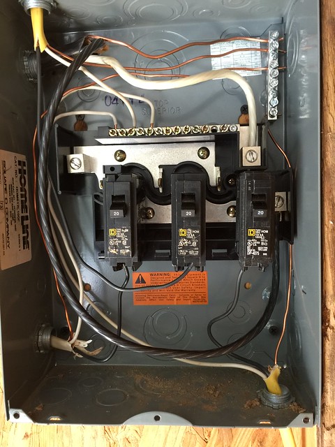
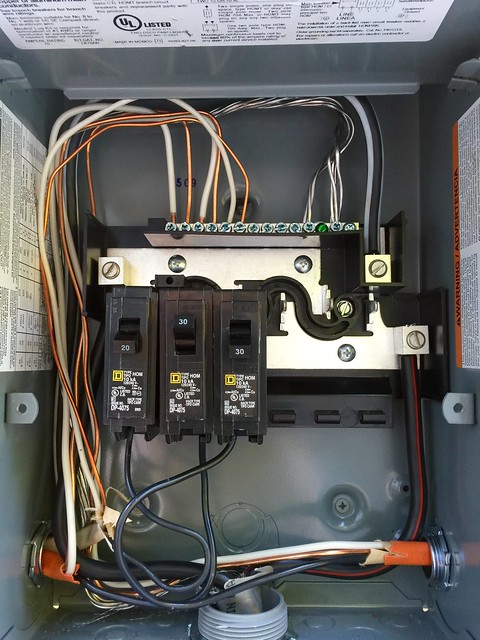
Eddie, read my post above yours again. I made an edit, and it contains important information. You have done a good job of fixing the screwups in the subpanel!
By the way, anytime you need electrical advice, the Mike Holt forum is the best source on the internet for information.
If you join the forum you'll be able to use the search function. It is a great tool for the DIY home owner.
http://forums.mikeholt.com/
By the way, anytime you need electrical advice, the Mike Holt forum is the best source on the internet for information.
If you join the forum you'll be able to use the search function. It is a great tool for the DIY home owner.
http://forums.mikeholt.com/
Last edited: