Nope. He's already meter-verified 120V between the white and black.
--Carlos V.
Oops......
But.... I "thought "someone said something about a double pole breaker....

Nope. He's already meter-verified 120V between the white and black.
--Carlos V.
If that were the case, I would have 240vac across the two wires, right?
I show 121vac, so hot and neutral, right?
5) Hook black to B with same gauge wire jumping to E
Yes. But only one side was used to back feed into the buss.Oops......
But.... I "thought "someone said something about a double pole breaker....
Yup
Edit....
F should be the white/ neutral.....
B should be the black wire / hot/....
*I would no longer have a cutoff. Should I maybe install one inline, or is it enough to just switch off breakers individually?
NO,, big time no.
Black wire (single phase) should be at (F) to feed all C/Bs from the buss, (unprotected) but he is back feeding the C/B which will do the same thing and limit the amperage coming in to 50 AMPs as he needs.
NO,, big time no.
Black wire (single phase) should be at (F) to feed all C/Bs from the buss, (unprotected) but he is back feeding the C/B which will do the same thing and limit the amperage coming in to 50 AMPs as he needs.
Yes. But only one side was used to back feed into the buss.
Someone really put some effort into getting this thing wired in the most wrong way possible.

Hmmmm..
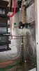
Looks to me the F lug is electrically connected to the neutral buss where all the small white wires are attached...
Follow the bright aluminum plate the F lug is attached to..

Ya know.....
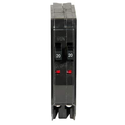
I have NEVER seen a 50 amp single pole breaker
Ya know. As soon as you make a statement like that, somebody's going to Google. *grin*
http://www.homedepot.com/p/Square-D-QO-50-Amp-Single-Pole-Circuit-Breaker-QO150CP/100153251
And it'll fit the OP's Square-D.
--Carlos V.
...But... What device uses a single pole 50 amps @ 120 V...
The OP's subpanel, for one.
--Carlos "I can do this all day" V.
But..... There are NO wires connected to the 50 amp single pole breakers...
I had my garage built about 7 years ago by a contractor/handyman/good ol' boy, who also wired it.
In any case, all the outlets and lights and garage door openers have worked fine.
But recently I wanted to add a breaker for an outdoor outlet and I'm a bit stumped.
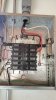
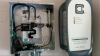
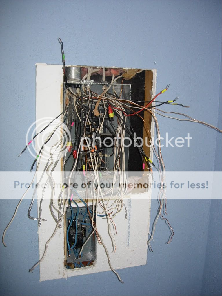
This is how the panel is wired:
Looks like he brought just one hot (black wire), one neutral (white wire) and a ground from our main panel via the upper left side punchout. Wired the hot to the 50A breaker screw at A. This is powering Bus D throughout the breaker. So the two 20A breakers work to supply everything via Bus D.
But the empty slots powered by Bus B provide nothing, having been hooked up to the neutral via terminal A.
Looks like he did it this way to provide a master breaker/cutoff.
Seems like the neutral should have gone to F for the neutrals and grounds, the hot to B and jumped to E (barely visible on the right) where a second hot wire would normally go. That would provide current to both busses, D & C. But with no master breaker.
Any thoughts? Is what's shown in the photo a common way to wire a breaker panel or just jury-rigged and wrong?
Thanks. I understand a bit about electricity and wiring but have not done very much with home wiring before.
I'm talking about the panel itself. The main panel can have a single pole 50A breaker to feed that 50A 120V single phase panel.
--Carlos V.
 ..
..The box is designed to have a 220v feed. The double 50 would have two wires coming in(one probably red) and it would span bus C and D providing 110 to each. The white neutral would go to F. He just made a 110 feed and used bus C with lug B for the Neutral. I think there may be a Code violation here that has to do with bonding subpanels to main panels. I don't remember if you are supposed to Bond or not Bond. He may have it right and by using bus C saved some wire. Not sure. Maybe thats answered above. I didn't take the time to read the whole thread.

It sure looks for all the world like the neutral was not hooked up to anything before - as such you guys are right that the return must have been through that unshielded ground wire.
You think I'm OK without a disconnect or master breaker here? There is a 50A breaker at my main panel.
One final thought...
How about stripping a bit of insulation off the black wire and running it through the buss terminal on the left on its way to the one on the right? Not now, necessarily, but if I ever need more circuits in the future.
Thanks for all the help so far!
the way that this is wired in this picture you have the white (neutral ground) and a black (single phase) giving you 115-120 VAC. with no floating ground to use the third finger of a grounded plug.OK, the fire trucks just left...
I keed, I keed!
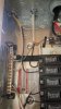
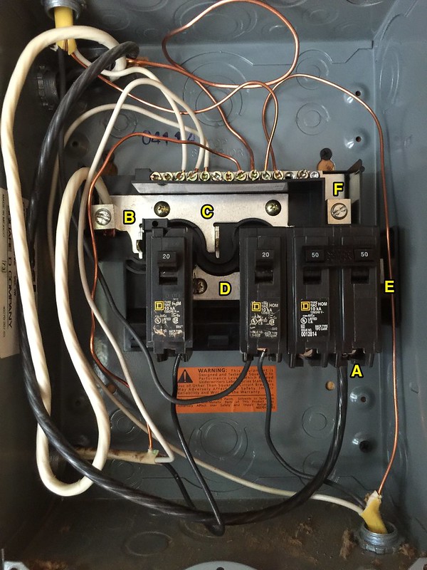
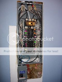
Seriously, this is where I'm at right now with everything working as it should and a separate breaker for each circuit:
It sure looks for all the world like the neutral was not hooked up to anything before - as such you guys are right that the return must have been through that unshielded ground wire.
Remember, I had nothing to do with the original setup. Things just seem pretty loosey-goosey here in the sticks.
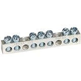
Tomorrow I'll get a separate buss and put the grounds alone on that.
You think I'm OK without a disconnect or master breaker here? There is a 50A breaker at my main panel.
One final thought...
How about stripping a bit of insulation off the black wire and running it through the buss terminal on the left on its way to the one on the right? Not now, necessarily, but if I ever need more circuits in the future.
Thanks for all the help so far!

the way that this is wired in this picture you have the white (neutral ground) and a black (single phase) giving you 115-120 VAC. with no floating ground to use the third finger of a grounded plug.
FWIW, all of the outlets (110 and 220) that I put into my garage are GFCI protected.
My bandsaw will occasionally trip one, but it reduces the worry of extension cords, outside, wet, etc.
That will be corrected when I isolate ground and neutral at the box, right?
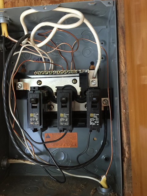
(with or without a ground fault button) to make sure that the ground /neutral / hot wires are connected to the appropriate prongs in the outlets that may have been installed when the garage was built...
That will depend upon how each circuit is wired the bare copper wire must be attached to a ground buss. separate from the white or black wires.That will be corrected when I isolate ground and neutral at the box, right?
That will be corrected when I isolate ground and neutral at the box, right?
Just keep in mind... As strange as it sounds,, The ground and neutral are at the same potential and eventually get connected together at the main panel before they head outside to the service entrance......
There should also be a ground rod driven 6' into the ground out side of the building and connected to the bare wire buss by a big copper wire. #6 or larger.
Good point. With the panel being willy-nilly, I would suspect polarity on the outlets will demonstrate the same lack of attention. (neutral/white should be on the long slot side)
--Carlos V.
OK, the fire trucks just left...
I keed, I keed!
Seriously, this is where I'm at right now with everything working as it should and a separate breaker for each circuit:
It sure looks for all the world like the neutral was not hooked up to anything before - as such you guys are right that the return must have been through that unshielded ground wire.
Remember, I had nothing to do with the original setup. Things just seem pretty loosey-goosey here in the sticks.
Tomorrow I'll get a separate buss and put the grounds alone on that.
You think I'm OK without a disconnect or master breaker here? There is a 50A breaker at my main panel.
One final thought...
How about stripping a bit of insulation off the black wire and running it through the buss terminal on the left on its way to the one on the right? Not now, necessarily, but if I ever need more circuits in the future.
Thanks for all the help so far!
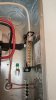
Get that F*****g bare ground wire on the right side right next to that hot lug over to the left side with the others!!!!!