In tracking down a charging issue I was measuring resistance across circuit breakers. One in particular had a good resistance reading but one terminal was loose. That is, it would wiggle slightly if pressed against. Is it due for replacement? It is this kind example . (I did try searching here but my search-fu wasn't working for this particular question.)

You are using an out of date browser. It may not display this or other websites correctly.
You should upgrade or use an alternative browser.
You should upgrade or use an alternative browser.
Circuit Breaker Test?
- Thread starter farmrjohn
- Start date

- Joined
- Dec 5, 2010
- Messages
- 6,581
- Display Name
- GeorgeC
Replace it.
I had a loose lug like that. I am thankful that it showed itself by causing my ALT INOP light to flicker (alt field breaker), rather than quietly wreaking havoc for years with an intermittent connection...
I had a loose lug like that. I am thankful that it showed itself by causing my ALT INOP light to flicker (alt field breaker), rather than quietly wreaking havoc for years with an intermittent connection...
Any loose parts on a circuit breaker signals a danger of failure to trip, or going open circuit, and being impossible to reset.
Thank your lucky stars that you found it on the ground. Much cheaper than if it failed in flight. You are not at a strange field hunting for a mechanic, and parts.
Thank your lucky stars that you found it on the ground. Much cheaper than if it failed in flight. You are not at a strange field hunting for a mechanic, and parts.
What was the "good resistance" value and did the resistance change when you moved the terminal?One in particular had a good resistance reading but one terminal was loose.
How old is the CB and what system is it protecting?
.1 ohm but didn't notice any reading change or movement of terminal while taking the reading, I noticed the movement later and didn't take a reading then.What was the "good resistance" value and did the resistance change when you moved the terminal?
How old is the CB and what system is it protecting?
I estimate the CB is OEM so 60 years. It appears it is the original generator CB "switch" that has an added 10 amp CB in the circuit for an engine/alternator conversion (C-90 to O-200 done in 1994 via 337 field approval). The original wiring from the switch went to terminal B on the generator voltage regulator. It now goes to terminal S on a Zeftronic R15v00-A regulator through the added 10 amp CB. The 10 amp CB is labeled "Voltage Regulator", the "original CB switch is labeled "Alt. Control".
What specific “charging issue” are you tracking down?It appears it is the original generator CB "switch" that has an added 10 amp CB in the circuit for an engine/alternator conversion (C-90 to O-200 done in 1994 via 337 field approval).
How and where is the 10A CB added in the 60A CB circuit?
What specific aircraft model and year?
Have you performed any voltage drop checks on the charging and battery systems?
I'm not seeing the 10A requirement in the R15V00 install diagrams. While I have my suspicions why its there, perhaps post a snapshot of Block 8 of the 337 for the install.
Last edited:
An Electronics International volt/amp meter is located in the battery feed. In addition there is a CGR-30P engine monitor and electronic flight instruments that have voltage warnings. For a couple of flights there would be a momentary low volts warning after engine start and after the battery re-charging was complete with a return to normal indications (near zero amps, 14 volts). After a couple of flight like that in flight shortly after takeoff the volts started fluctuating between 13-15.6, verified on the V/A-1 and CGR-30P along with the volts warning lights on the flight instruments. I turned off the alternator via the above mentioned switch/CB and landed. Following the troubleshooting advice on the forum we checked the continuity of the field wire and "A" wire between the alternator and regulator. Everything checked good. A ground test run indicated everything back to normal with the amps showing a charge after engine start @ 14 volts, dropping to near 0 amps as the battery charged with volts still at 14. The next flight the amps never dropped below 2.4 and the voltage stayed between 13.6-13.8. I aborted the flight and after taxiing in, left the engine running with alternator on while switching off all other electrical loads. There was no change in the volts and amp reading. The battery is an EarthX 680C (installed with 337 field approval) and we checked that with the recommended Optimate lithium charger per EarthX's procedures which indicated full charge and optimized cells and charge holding. The battery also had a successful load test at the last annual in August.What specific “charging issue” are you tracking down?
The 10 amp CB is added to a 35A CB/switch, not the 60A alternator CB. It's located about 1 foot away from the original.How and where is the 10A CB added in the 60A CB circuit?
'66 Alon A2What specific aircraft model and year?
Battery check/tested per above. We haven't run the engine since the Optimate charge sequence. Have followed the Zeftronics troubleshooting checklist with exception of engine running measurement. The field to ground resistance check was 6.4 ohmsHave you performed any voltage drop checks on the charging and battery systems?
The STC they used as a basis for approval did not include the Alons at that time. The electrical systems are different between the models. Block 8 does not mention adding the 10A CB. I'll also include the original and current Alon electrical schematics. The top portion of the master switch is no longer used. The alternator is a PlanePower (Hartzel) ES4001 and has approximately 350 hours on it since new in March 22.I'm not seeing the 10A requirement in the R15V00 install diagrams. While I have my suspicions why its there, perhaps post a snapshot of Block 8 of the 337 for the install.
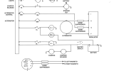 .
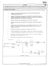
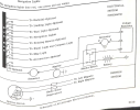
So all your troubleshooting voltages are only based off the readings on the EI and CGR indicators?An Electronics International volt/amp meter is located in the battery feed. In addition there is a CGR-30P engine monitor and electronic flight instruments that have voltage warnings.
CBs only protect the wiring and not the device. Have 2 CBs of different ratings inline on the same wire is a big no-no. So to verify, are you 100% positive the 10A CB is installed inline as per your diagram below, or could it possibly be a wire is spliced to the 35A control circuit wire and that wire feeds the 10A CB to parts unknown?The 10 amp CB is added to a 35A CB/switch,
Voltage drop checks are performed static without the engine running. Using the Zeft troubleshoot doc and a VOM, what are the volts at the indicated points per Page 2, items 1 and 2.Have followed the Zeftronics troubleshooting checklist with exception of engine running measurement.
The engine alteration and 337 have zero to do with your issue.The STC they used as a basis for approval did not include the Alons at that time.
No, those reading were in flight. The ground troubleshooting was done with a multimeter.So all your troubleshooting voltages are only based off the readings on the EI and CGR indicators?
Agree. In discussion with AP/IA on replacing the 35A CB/switch with a 10A CB/Switch and removing the additional 10A CB. The wire from the existing 10A CB does go to terminal S on the Zeftronic and appears "new" going from the 35A CB/switch.CBs only protect the wiring and not the device. Have 2 CBs of different ratings inline on the same wire is a big no-no. So to verify, are you 100% positive the 10A CB is installed inline as per your diagram below, or could it possibly be a wire is spliced to the 35A control circuit wire and that wire feeds the 10A CB to parts unknown?
Had used the checklist on page 4 that includes the Alt post F voltage. Results:Voltage drop checks are performed static without the engine running. Using the Zeft troubleshoot doc and a VOM, what are the volts at the indicated points per Page 2, items 1 and 2.
Bat. On/Alt. off: Bus 13.58, Pin I: 0, Pin A: 13.58, Pin S: 0, Pin F: 0, Alt post F: 0
Bat. On/Alt on Bus 13.28, Pin I: 12.99, PIn A: 13.05, Pin S: 13.18, Pin F: 12.79, Alt post F: 11.95
Included the 337 per request since that is when the plane was converted from a generator to alternator, and I suspect that 10A CB was added at that time . There is no other reference in the logs.The engine alteration and 337 have zero to do with your issue.
Back to my original question on replacing the CB with the loose terminal, the parts manual calls for a Wood Electric 112-235-101 CB. Are those the same dimension as the W23/W31 series linked above?
Are you positive the bus voltage is 13.58? Given the battery open circuit voltage EarthX spec shows 13.20, your VOM may be off. And based on what you posted that meter error may be why a couple of your voltage test values are off. However, given you have non-standard wiring installed for that system, I would bring the alternator and battery wiring back to spec for the Zeft and Plane alternator alterations before anything else then retest with an accurate VOM.Bat. On/Alt. off: Bus 13.58, Pin I: 0, Pin A: 13.58, Pin S: 0, Pin F: 0, Alt post F: 0
As I recall the W23/W31 series are the updated part numbers for the Wood 112 series after Tyco bought Wood. Regardless, here's a link to the W series spec sheet which you can compare dimensions to your older Wood CB dimensions. And just to add, the loose terminal could possibly be due to the potting compound has loosened but the CB is not electrically compromised. However, replacing a 60 year old CB is usually a good preventive measure in most cases.Back to my original question on replacing the CB with the loose terminal, the parts manual calls for a Wood Electric 112-235-101 CB. Are those the same dimension as the W23/W31 series linked above?

bnt83
Final Approach
There may be moments when the voltage regulator is applying zero volts to the field, and somehow the CGR-30P only picks that up once in a while as the sampling rate is pretty slow IMHO.
I have legacy strobe power supply that puts an 8 amp intermittent load on a 60 amp bus, volts and amps readings on the CGR are never gonna be flat dead numbers. Power it all up, lights, strobes, pitot heat, and then start moving the electric flaps too..
I have legacy strobe power supply that puts an 8 amp intermittent load on a 60 amp bus, volts and amps readings on the CGR are never gonna be flat dead numbers. Power it all up, lights, strobes, pitot heat, and then start moving the electric flaps too..

Dan Thomas
Touchdown! Greaser!
- Joined
- Jun 16, 2008
- Messages
- 12,389
- Display Name
- Dan Thomas
.1 ohm is pretty small for the average meter to be measuring. The test leads alone can offer that much resistance. What does the meter say when you short the lead tips?.1 ohm but didn't notice any reading change or movement of terminal while taking the reading, I noticed the movement later and didn't take a reading then.
The old analog meters had a zeroing function to make the meter read zero when the leads were shorted. I haven't seen a digital meter with that yet. But maybe there are some...
Anyway, that .1 ohms is not your problem, not in a smaller breaker. Those breakers have some resistance so that heat is generated in their bimetal components so that they will trip off at the engineered amperage. A low-amp breaker needs a bit more resistance than a 60-amp breaker does to generate the heat.
The loose terminal could be the problem. One of the terminals is one of the breaker's contacts, and the other it attached to the bimetal strip. Time to replace it. Loose stuff means intermittency.
Depending on the wiring and the type of regulator, that alternator field breaker handles very little current. It feeds the switch that connects to the S terminal on the regulator, and that terminal is only attached to the small coil on a small relay that turns the regulator on. The field current comes from the alternator output, or the bus, not the ALT breaker or switch. Like so:
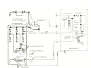
An electronic regulator could need more current from the switch, such as in the common electronic regulators used by Cessna starting in the late '60s:
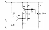
The "B" (battery) terminal is switched on by the switch, and the field current comes through it.
Some electromechanical regulators were wired more like the electronic ones, with the field power coming from the ALT switch. Piper:
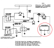
Or Lake:
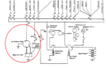
A 12-volt alternator's field will draw maybe 4 amps, so the breaker doesn't need to be big.
Dan Thomas
Touchdown! Greaser!
- Joined
- Jun 16, 2008
- Messages
- 12,389
- Display Name
- Dan Thomas
I can think of no good reason why an electronic regulator would need to be so slow. Even the electromechanical regulators respond almost instantaneously. If the field voltage is jumping around due to slow field response, it will cause other problems such as flickering lights or avionics problems.There may be moments when the voltage regulator is applying zero volts to the field, and somehow the CGR-30P only picks that up once in a while as the sampling rate is pretty slow IMHO.