At this point its a survey of the job and data.
A guy could try and make a shim to go between the G5 and the gyro panel but it would need to be pretty thick and the plastic overlay would need a giant hole cut into it to prevent sandwiching the overlay between the G5 and the floating panel which would basically attach the overlay to the floating panel and defeating the purpose of the shock mounts.
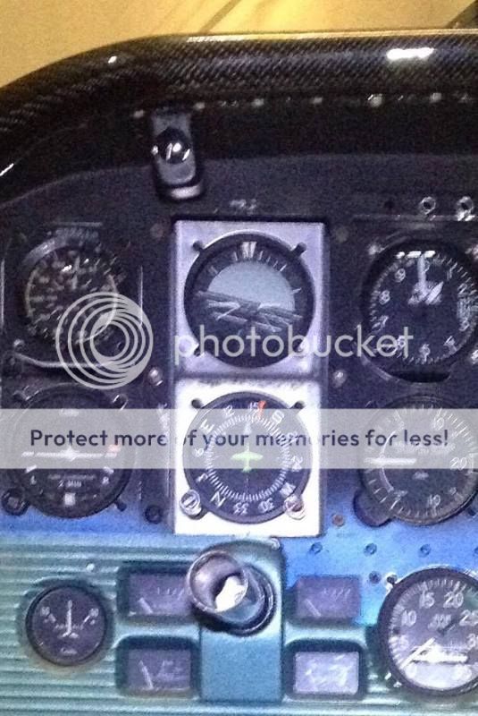
Says in Limitations 2.1 cannot be installed in a shock mounted panel, so not an option anyway.
You can't just fabricate something at random to mount it on./QUOTE]
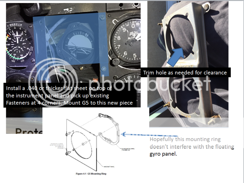
That's basically what the OEM did to mount the TC gyro. There is a separate formed piece to offset the gyro by X degrees, rigidly attached to the fixed panel using four MS210470AD-4 rivets.
If the four shock mounts with brass posts attached with brass nuts that can support the entire gyro panel + two gyros + hoses, then there shouldn't be a problem taking the vacuum gyro out of it.
Adding a sheet that picks up the those four existing fasteners seems most logical. If lined up well with the original attitude indicator hole there should be clearance around the G5 and the floating panel which would be immediately behind it but not attached to it. Worse case is trim the floating panel hole a bit to increase clearance.
Since this would rigidly mount the G5 to the larger fixed panel it would not have the ~6 degree offset but that will be compensated for during calibration/setup and within installation manual specs. Also, since the G5 would not be floating, there should be no issues letting the plastic overlay extend under the G5 bezel so should not need to cut a giant hole in it.
It appears that electrical bonding of the G5 to the mounting ring is ensured by the guide pin on the top of it as there is no mention of bonding straps in the manual or even bonding check.