Alternator Mounting Problem

Rob58

Pre-takeoff checklist
Joined
Feb 20, 2016
Messages
360
Display Name

Display name:
Rob
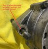
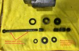
Noticed my alternator (ES-4011) has a fair amount of movement in the lower bracket attach point contributing to excess vibration and wear. I pulled the unit and examined all of the mounting hardware and discovered several problems as shown. Trying to find an assembly drawing but Hartzell tech support isn’t too helpful. Not sure the existing mounting hardware is even correct – looks like a random collection of bushings and washers. I do understand there are rubber bushings to help dampen vibration but unsure how these are implemented or where to find replacements. Any comments or suggestions are much appreciated!

Alternator Case Hole.jpg
Alt Mounting Hdwr.jpg
 
Would not be surprised if there was a mismatch of bolt hole sizes between the alternator and the engine.

Is this the consequence of a botched generator to alternator conversion? You may need new bolt to fit the alternator and new brackets too.

My alternator bracket has no spacers added. (Lycoming O320 with front mounted Ford flavor)
 
Noticed my alternator (ES-4011) has a fair amount of movement in the lower bracket attach point contributing to excess vibration and wear. I pulled the unit and examined all of the mounting hardware and discovered several problems as shown. Trying to find an assembly drawing but Hartzell tech support isn’t too helpful. Not sure the existing mounting hardware is even correct – looks like a random collection of bushings and washers. I do understand there are rubber bushings to help dampen vibration but unsure how these are implemented or where to find replacements. Any comments or suggestions are much appreciated!

View attachment 122809
View attachment 122810
When was the last time the alt was rebuilt? It looks like it is time to have it overhauled? The overhaul shop may be able to provide new and proper hardware for your application?
Definitely need a new bolt. What is the application and where are you located?
 
Bellanca Viking? Continental O- or IO520. Continental had two different generator/alternator mounting systems. The earlier one had a cushioned system, with rubber mountings, and the adjusting arm was also cushioned at its engine end. Later models were mounted more like Lycomings, rigidly, including the adjusting arm, and that bolt/nut in the OP's picture was tightened up to clamp the alternator securely between the mounting bracket ears.

Someone has mixed up the parts from both systems there. I've see this a couple of times before, and it always results in destruction of the alternator's case. The OP's mechanic needs to consult the Continental parts catalog for those engines and get the right parts and get the system sorted out properly. Mixing and matching saves money, for a little while, and then the real bill comes due. Ouch.

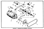
An example of the cushioned system:

1701270108188.png

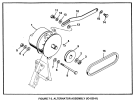
The rigid system:

1701270144829.png

Getting it right might mean a change to the left rear engine mounting bracket.
 
Thanks for the feedback! This alternator was installed about 550 hours ago as a generator to alternator upgrade on my Commander 500A Colemill. Engine TCM IO520-E. I agree that someone likely mixed up some of the parts and that's what I am trying to figure out. Even with the vibration problem the alternator is producing the expected output power. I will consider having the unit overhauled but still need to figure out the correct mounting configuration. I will take a picture of the mounting bracket as attached to the engine and post that tonight. (PS - my Viking with IO-520-D still has a generator and runs just fine)
 
I’ve seen similar problems a few times and it generally comes from mixing and matching parts like Dan suggested above or from a neglected or improperly assembled rubber mounted system. In every case I’ve dealt with it has worn out the mounting ear just like yours is.
 
Thanks for the feedback! This alternator was installed about 550 hours ago as a generator to alternator upgrade on my Commander 500A Colemill. Engine TCM IO520-E. I agree that someone likely mixed up some of the parts and that's what I am trying to figure out. Even with the vibration problem the alternator is producing the expected output power. I will consider having the unit overhauled but still need to figure out the correct mounting configuration. I will take a picture of the mounting bracket as attached to the engine and post that tonight. (PS - my Viking with IO-520-D still has a generator and runs just fine)
It is recommended to inspect replace brushes at 500 hrs and with the vibration you have experienced I would want it inspected while it is off the plane.
Good luck getting back on the plane hopefully running smooth.
 
Is there a fix for that?

Aside from replacement, there’s Probably not a terribly cost effective one for most people. We’ve bored and sleeved one for an owner who owned a machine shop but that would likely not be practical in most cases.
 
Hey Rob, I had this happen on the 67 Vike with an IO-520K.
A rancher with machining knowledge reamed and bushed the holes for me in about 30 minutes - with a new bolt - and it went for 800+ hrs after that. I checked for any looseness annually for several years and the problem was fixed.
I did have the rotating mass balanced - some said that was the problem.
Not sure what fixed it but I’m putting my money on the fact that I bought a used, repaired one (new bushings) and stored that all those years.
 
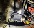
Picture of the mounting bracket below. I'm assuming all of the black dust is from the brushes. Hi Dave - good to cross paths... hope all is well!

Part of my conundrum here is to understand the role of a rubber washer or rubber bushing. Does a rubber part even belong in this assembly? If so is it intended to dampen vibration in an axial direction or should it completely suspend the alternator from any contact with the mount bolt and bracket? I certainly have the facility to bore the case and make this a close tolerance metal-to-metal fit. This is why I am searching for some documentation to see what the design intent was. Thanks for everyone's help!!

Alternator Bracket.jpg
 
My rear-mounted, belt-driven alternator was metat on metal at all contact points.
 
I'd find an engine and airframe parts manual and just start googling and ebay searching part numbers and studying pictures.
 
Part of my conundrum here is to understand the role of a rubber washer or rubber bushing. Does a rubber part even belong in this assembly? If so is it intended to dampen vibration in an axial direction or should it completely suspend the alternator from any contact with the mount bolt and bracket?

The washers that you have look like they were only to help dampen vibration transmission. But looking at the above diagram, looks like the isolated one (top diagram), the top mount was to prevent any metal to metal contact at that point.

I would think the actual goal should be like the bottom one where it is metal to metal and everything just kinda vibrates in harmony.
 
Part of my conundrum here is to understand the role of a rubber washer or rubber bushing. Does a rubber part even belong in this assembly? If so is it intended to dampen vibration in an axial direction or should it completely suspend the alternator from any contact with the mount bolt and bracket? I certainly have the facility to bore the case and make this a close tolerance metal-to-metal fit. This is why I am searching for some documentation to see what the design intent was. Thanks for everyone's help!!

I can't speak with absolute confidence on what the design intent was but I've always assumed that the rubber isolators were intended to keep the alternator vibration from being transmitted to the engine/crankcase. Between using a drive belt and the rubber cushions, the alternator should be pretty isolated.

Perhaps it is an apples and oranges comparison but the Lycoming engine crankcases take a real beating from the solid mounted alternators and cracks can form in that area as a result. Continental may have been trying to avoid a similar situation.
 
Picture of the mounting bracket below. I'm assuming all of the black dust is from the brushes.
The black dust is oxidized aluminum ground off the alternator case. Way too much dust for brushes.

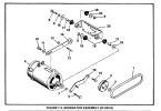
This is similar to what you have, but without all the right bushings and hardware. The black things identified as "18" are rubber bushings.

1701386912595.png

Now, that is for the generator mounting. The generator had two mounting ears, so two shorter bolts were used, along with bottoming spacers (17), washers and nuts. Your alternator has one long mounting lug, and someone hamburged it all together with an assortment of spacer and washers and junk and a long bolt, and it shook loose and made that mess. Not acceptable, never was airworthy.
I can't speak with absolute confidence on what the design intent was but I've always assumed that the rubber isolators were intended to keep the alternator vibration from being transmitted to the engine/crankcase. Between using a drive belt and the rubber cushions, the alternator should be pretty isolated.
Other way around. It was to keep the engine from shaking the daylights out of the alternator. That alternator gets topnotch balancing when it's built; it turns at up to 10,000 RPM and is very smooth. But the shockmounted alternator was a pain; it would sometimes jump around so much that the belt would get thrown off.
Perhaps it is an apples and oranges comparison but the Lycoming engine crankcases take a real beating from the solid mounted alternators and cracks can form in that area as a result. Continental may have been trying to avoid a similar situation.
I looked after a lot of Lycomings, and the cases never got damaged. If the alternator bracket wasn't torqued up properly it sure could get torn up, broken bolts and all. That bracket had a habit of cracking at the bends, though. It's made of maybe 1/4" steel plate with really tight-radius bends, and if the cut edges weren't properly dressed before bending, it would get tiny cracks that would grow.

1701386556351.png
 
Other way around. It was to keep the engine from shaking the daylights out of the alternator. That alternator gets topnotch balancing when it's built; it turns at up to 10,000 RPM and is very smooth. But the shockmounted alternator was a pain; it would sometimes jump around so much that the belt would get thrown off.
If that were the reason I don't think we'd be seeing almost every modern automotive alternator being equipped with a one way clutch. Both the alternator shaft and the engine crankshaft (or in the case of a Continental the starter adapter shaft) will accelerate and decelerate, at different frequencies. Having the alternator driven by a belt helps but it obviously isn't always enough.

I looked after a lot of Lycomings, and the cases never got damaged. If the alternator bracket wasn't torqued up properly it sure could get torn up, broken bolts and all. That bracket had a habit of cracking at the bends, though. It's made of maybe 1/4" steel plate with really tight-radius bends, and if the cut edges weren't properly dressed before bending, it would get tiny cracks that would grow.

So have I, and I've overhauled a lot of them too. I don't recall ever seeing an alternator bracket that cracked but I've seen a number of threads pulled out of the crankcase for the alternator bracket. I'm not convinced it is always a case of improper torque. Some applications/designs are likely more prone to cracking than others, considering how many different styles of alternators and generators have been on these engines.
 
IIRC the “link“ between the Starter and Alternator is an “Option” for Lycomings.

Having also seen bolts pulled that makes no sense to me.

There is also an improved mount that is quite an improvement.
 
If that were the reason I don't think we'd be seeing almost every modern automotive alternator being equipped with a one way clutch
When did they start doing that?
I don't recall ever seeing an alternator bracket that cracked but I've seen a number of threads pulled out of the crankcase for the alternator bracket. I'm not convinced it is always a case of improper torque.
Too much belt tension. The service manuals have a specification for the tension: so many foot-pounds on the alternator pulley nut to make the belt slip. It makes the belt somewhat less tight that one would be expecting.
IIRC the “link“ between the Starter and Alternator is an “Option” for Lycomings.
Never saw one without it.
 
They’ve been commonplace for at least 20 years.
Hm. Neither my 2007 Ford Ranger nor my '06 Hyundai Sonata has it. Maybe my vehicles are just too old and cheap...
 
The likely reason for a one-way clutch in cars would be a way to prevent torsional crankshaft vibration from being reflected/applied to the alternator armature. I've never heard of this sort of thing before either, but vibration amplitude limiting would be the effect of a one way drive clutch. It may be a reflection of factory opinion of the casual nature of auto repair work, where the field belt tension is probably expected to be done by guess and by gosh, and no amount of otherwise fancy isolation hardware is going to be properly serviced in the field. A one way clutch would be bomb proof but it would seem to me to be excessively exotic otherwise. Cars etc run over widely varying rpms too, and the one way clutch thing would be effective over a wide range of rpms. Aircraft engines essentially run at fixed rpm.

On the IO 520 rubber isolation system described above, rubber (elastomers is a better word....) is almost always dynamically loaded in shear if it is to provide isolation or damping. Opposed aircraft engines squiggle (rock) about their yaw axis at high frequencies (especially twice crankshaft rpm for any 4 cyl engine). The 520 CID 6 cyl should be fairly smooth unless there is a major internal imbalance involving the moving mass CG. The ride given to anything case-mounted gets wild as you get away from the engine CG though. It has to be this vibration mode that is anticipated with the elastomeric sheets or bushings in this application. But imagine the change in elastomeric characteristics with temperature or when a generator is casually replaced by lighter weight alternator. Probably some field 'engineering' was involved.
Good reply. You win today's internet answer.

 
Quick update - I have been persistently reaching out to Hartzell in addition to the STC owner attempting to obtain documentation on the correct installation configuration. I was pleasantly surprised to actually receive a personal response from Hartzell with the promise to conduct some research on this. Thanks to all who have helped with this issue thus far. Will continue updating until problem is solved!
 
Back
Top