
Let'sgoflying!
Touchdown! Greaser!
I have a flowmeter and a fuel pressure sender both of which are intermittent.
I can't tell if they are defective or if it is a wiring/connector problem.
Both have been replaced about 3 years ago (the flowmeter was dead after an engine overhaul and years of downtime; the pressure sender seemed to have just quit and worked for a while after that).
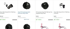
They both feed via wiring and AMP or AMP-like connectors (photo) to a device that has raw displays, an "EAU" and this sends the data to a pair of (yes, old) Cheltons which work find otherwise.
When the readouts are abnormal, both the EAU and Cheltons show failure so I want to start with the senders and the wiring/connectors.
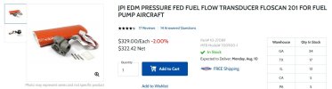
The fuel flowmeter is a JPI model (photo) and I have no reason to think its failed so soon.
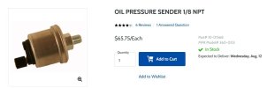
The pressure sender is a VD0 oil pressure sender which apparently was common at the time of building this model EXP.
(photo) It has a single wire and a ground wire soldered to the case which is secure and I have confirmed a good ground to the battery's ground.
To test the flowmeter and pressure transducer I was thinking I could run the engine and while they were electrically disconnected from the airframe, have a VOM connected to them see if they are putting out whatever range of voltage (or maybe resistance) expected.
Maybe I could likewise leave them disconnected and provide some safe range of voltage(?) to their connectors and see if there is an expected display on the panel?
Just trying to avoid the parts cannon by doing some actual testing; send ideas.
Lancair IV
28V
TSIO-550-E