Stalls and leading edge questions

Over on another forum it was suggested that I put together some numbers so that I could have a talk with my local FAA DER. I am ok but not great with computers, so I was wondering if one of you guys out there likes to tinker with airfoil analysis on a computer? If so would you be willing to look at a few airfoils and run some numbers for me?

One Miracle at a time.

Thank you in advance.
 
Maybe, but not my first choice. I prefer not to add VGs just to soften the stall a bit. If I was going for full out STOL, then I might consider that, but I'd be looking for another airplane first.

they do far more than that! They “tighten up” the “steering”....

what I mean by that, at least for my old bird is they make the controls crisp feeling damn near to taxi it seems. I love them for landing as the controls do not get mushy...
 
You shouldn't be stalling on landing either. "Full stall" landing is a myth.

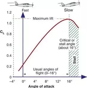
They say that being “technically correct” is the best kind of correct! And you may be. But the stall is often defined as that region where any further increase in angle of attack causes a decrease in lift.

50681751728_d6cc89f4f1_o.jpg


When landing slowly enough, you get to a point that in spite of pulling the stick back farther, lift dissipates to the point where the plane lands regardless. In a taildragger with the tailwheel rolling on first, the “stall” and the drop of the mains to the runway with the stick all the way back sure feels like a stall.

Enough so that the term “full stall landing” is immediately understood by most pilots, even if not “technically correct”. And I’ll continue to use it. So there!
 
Last edited:
You have defined the stall properly in your line before the graph, but what you say after it is incorrect. Running out of sufficient lift to hold the plane in the air is NOT the same as stalling. Lift is a function of AOA and the speed, so yes, when you slow you can hit the ground because there's not enough lift, but this happens ahead of the point of stall. Unless you drop it in, it's not possible (certainly not in a tricycle gear, and not in most taildraggers either) to have the mains on the ground and be at a stall angle of attack.

Further, the lift vs. angle of attack curve is fairly symmetrical around the critical angle. Hitting the stall isn't the point where lift goes away completely and the plane drops in. The reason they don't show the curve much above the stall point in your graph is that the drag goes up so high that there's not sufficient power to maintain level flight at those angles.
 
So, all of you that think I am an idiot and should drop the idea all together may just get your wish. IF I want to modify my bird THEN I will have to show an FAA DER exactly what I intend to do and why. I would have to produce engineering materials and or drawings and show reasonably accurate expectations of before and after performance. Right now I am stopped. The published airfoil data for the NACA 63-215 airfoil shows a sharp drop in lift at the end of the top of the lift curve. This information was likely generated in a wind tunnel and matches what I noticed practicing stalls at altitude. I got a airfoil program and it shows a nice smooth rounded transition from flying, over a 4 degree spread. That is NOT reality for that airfoil. If I can't predict accurate airfoil performance with a computer before building then I can't proceed. Simple as that. Right now I am frustrated. So I am stopped.
 

Attachments

  • PIC.jpg
    PIC.jpg
    236.7 KB · Views: 8
Last edited:
They say that being “technically correct” is the best kind of correct! And you may be. But the stall is often defined as that region where any further increase in angle of attack causes a decrease in lift.

50681751728_d6cc89f4f1_o.jpg


When landing slowly enough, you get to a point that in spite of pulling the stick back farther, lift dissipates to the point where the plane lands regardless. In a taildragger with the tailwheel rolling on first, the “stall” and the drop of the mains to the runway with the stick all the way back sure feels like a stall.

Enough so that the term “full stall landing” is immediately understood by most pilots, even if not “technically correct”. And I’ll continue to use it. So there!
You have defined the stall properly in your line before the graph, but what you say after it is incorrect. Running out of sufficient lift to hold the plane in the air is NOT the same as stalling. Lift is a function of AOA and the speed, so yes, when you slow you can hit the ground because there's not enough lift, but this happens ahead of the point of stall. Unless you drop it in, it's not possible (certainly not in a tricycle gear, and not in most taildraggers either) to have the mains on the ground and be at a stall angle of attack.

Further, the lift vs. angle of attack curve is fairly symmetrical around the critical angle. Hitting the stall isn't the point where lift goes away completely and the plane drops in. The reason they don't show the curve much above the stall point in your graph is that the drag goes up so high that there's not sufficient power to maintain level flight at those angles.
And to complicate things further, designers also add washout to the wings, and sometimes don't use the same airfoil along the wingspan. In the link below, they varied the thickness-to-chord ratio from the root to the tips. I've seen noted where two airfoils were blended along the span, transitioning from one to another.

https://www.aerosociety.com/media/4843/the-spitfire-wing-planform-a-suggestion.pdf
 
So, all of you that think I am an idiot and should drop the idea all together may just get your wish. IF I want to modify my bird THEN I will have to show an FAA DER exactly what I intend to do and why. I would have to produce engineering materials and or drawings and show reasonably accurate expectations of before and after performance. Right now I am stopped. The published airfoil data for the NACA 63-215 airfoil shows a sharp drop in lift at the end of the top of the lift curve. This information was likely generated in a wind tunnel and matches what I noticed practicing stalls at altitude. I got a airfoil program and it shows a nice smooth rounded transition from flying, over a 4 degree spread. That is NOT reality for that airfoil. If I can't predict accurate airfoil performance with a computer before building then I can't proceed. Simple as that. Right now I am frustrated. So I am stopped.
Why would you need to provide lift/drag performance simulations? Structural calculations, yea. But if you had to provide performance data up front, then there would not be any aftermarket wing tips or STOL kits on the market. That's what flight test is for. Experimental research and development...
2D airfoil simulations pretty much suck at predicting separation / stall behavior. The comparison of lift/drag during cruise might be useful to guestimate how much speed you will lose with the droop. You might be able to show the likelihood of being able to achieve a higher lift coefficient, but predicting stall behavior, not so much. And it gets more worser when you are trying to work with laminar flow airfoils - surface roughness, panel seams, bugs, all have a huge effect on the extent of laminar flow and separation. Even wind tunnel data is somewhat suspect when it comes down to the detailed shape of the lift curve near the stall - I don't have my copy of Abbot and VonDoenhoff handy (it's at work) - but a look at the difference between the data for smooth and rough models on some of the laminar airfoils.
 
And to complicate things further, designers also add washout to the wings, and sometimes don't use the same airfoil along the wingspan. In the link below, they varied the thickness-to-chord ratio from the root to the tips. I've seen noted where two airfoils were blended along the span, transitioning from one to another.
Somewhere back in this thread the (different) Mooney root and tip airfoils are given.
 
But the stall is often defined as that region where any further increase in angle of attack causes a decrease in lift.

First, that is not the correct definition. CL is not lift. CL is only one ingredient of the lift equation, along with several others, such as airspeed. It's possible for lift to decrease while Increasing angle of attack if the airspeed is decreasing factor.

When landing slowly enough, you get to a point that in spite of pulling the stick back farther, lift dissipates to the point where the plane lands regardless.

Aside from the previous flaw in your argument, here you are buying into the misconception that if the airplane is descending it must be because lift is less than weight, which is not true.
 
Unless you drop it in, it's not possible (certainly not in a tricycle gear, and not in most taildraggers either) to have the mains on the ground and be at a stall angle of attack.

. . .

Hitting the stall isn't the point where lift goes away completely and the plane drops in.

Setting aside the apparent contradiction for a moment, are you saying that when my taildragger is sitting on the ramp, the wing is not stalled?
 
Setting aside the apparent contradiction for a moment, are you saying that when my taildragger is sitting on the ramp, the wing is not stalled?
Correct. Many taildraggers can take off in a three-point attitude. It's the short field procedure in the 170, for example. Why would you think it was stalled?
 
Correct. Many taildraggers can take off in a three-point attitude. It's the short field procedure in the 170, for example. Why would you think it was stalled?
Isn't the angle of attack based on the relative wind? So a wing in the three point attitude may or may not be stalled depending on differences in the relative wind. Like the differences in landing and taking off.
 
So, all of you that think I am an idiot and should drop the idea all together may just get your wish. IF I want to modify my bird THEN I will have to show an FAA DER exactly what I intend to do and why. I would have to produce engineering materials and or drawings and show reasonably accurate expectations of before and after performance. Right now I am stopped. The published airfoil data for the NACA 63-215 airfoil shows a sharp drop in lift at the end of the top of the lift curve. This information was likely generated in a wind tunnel and matches what I noticed practicing stalls at altitude. I got a airfoil program and it shows a nice smooth rounded transition from flying, over a 4 degree spread. That is NOT reality for that airfoil. If I can't predict accurate airfoil performance with a computer before building then I can't proceed. Simple as that. Right now I am frustrated. So I am stopped.

For the record I don't think you are an idiot, quite the opposite actually. I just think the airplane is a non issue for the problem you describe. Sometimes it's easier to look toward the easy solutions.
 
Isn't the angle of attack based on the relative wind? So a wing in the three point attitude may or may not be stalled depending on differences in the relative wind. Like the differences in landing and taking off.
While it's possible that there are small variances in it, the relative wind of an aircraft on the ground is preponderantly parallel to the runway.
 
I missed that Riblett put a performance curve for the GA cuff on the next page. I think I got it confused with the evolution of GA airfoils, which looks similar. See attached.

1. There is an improvement in climb performance and extension of the laminar bucket.

2. The stall is softened considerably and extended.

3. There is indeed a drag penalty at high speed cruise of about 2% drag, or about 2 at 200.

4. There is no drag penalty at economy cruise.

5. The estimated weight addition is only 6 lbs based on .050" skin over 2lb density foam.

I still think this bears further investigation, even if I am the only one.
 

Attachments

  • Mooney 64 wing cuff performance .pdf
    138 KB · Views: 5
Drag buckets....
Difficult to maintain the wind tunnel model surface quality (an thus, the laminar flow) in a riveted aluminum airplane. Sailplanes with composite wings can get there, but often a lot of long board sanding is involved to get the most out of it. Compare rough vs. smooth on this page https://history.nasa.gov/SP-468/ch5-2.htm

(Image does not want to show up here...)

But, that is not to suggest that there is nothing to be gained - it's just that it will take some careful measurements in flight to quantify the change.
This may be of general interest: https://history.nasa.gov/SP-468/contents.htm
 
Back
Top