OAT probe packaging

GeorgeC

Administrator
Management Council Member
Joined
Dec 5, 2010
Messages
6,581
Display Name
GeorgeC
This is more of an EE question than an avionics question. The OAT on my Insight went tango uniform, so I poked at the probe a little, figuring I'd need to replace it anyway. I tried to unscrew the can, but it just kind of popped off, with what looked like a bit of rubber cement residue.
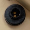
On the plane side, there are two gold contacts:
IMG_3229.JPG
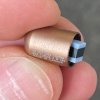
On the probe side, there's a rubbery rectangular block:
IMG_3230.JPG
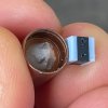
If I pull out the block, you can see the leads, with the device itself buried in potting compound:
IMG_3231.JPG
Note that the leads stick into but do not penetrate through the rubbery block.

I put it back together, and it worked again, at least for a little while.

Now, I might understand it if the black part of the block was an insulator, and the blue parts were conductive, and the leads stabbed into the blue parts, completing the circuit when pressed against the gold contacts... but both leads are stabbed into the black part.

It's designed to be replaced as a unit. Why bother with all of this? Why not just fill the whole can with potting compound and run the wires out?

@Half Fast?
 
but both leads are stabbed into the black part.

As a SWAG, I would say that your probe is a thermistor and the black material is a resistor with a specific temperature coefficient. I'd bet if you measured the resistance across the two leads while you placed the probe into hot water and then into ice water, you'd see a dramatic change in resistance.

With a little googling, you can read more than you'll ever want to know about thermistors. All resistors have a temperature coefficient and the resistance changes with temperature, but typically it's a very small effect, so that a 10k ohm resistor stays close to that value over a wide range of temperatures. In a thermistor, though, a resistive material is chosen that has a large temperature coefficient, one that is well characterized and accurate from one device to another.
 
So the blue parts are conductive and should be aligned with the gold contacts? If both leads stab into the black material, and If the black material is the one with the carefully chosen k, then what are the leads for? I figured the rubbery material was for vibration isolation/thermal expansion...

I'll have to bring it home and break out ye olde DMM.
 
If my guess is correct, the leads are the electrical connections to the thermistor material (black) (like the leads coming off an ordinary resistor) and the gray stuff is probably something with good thermal conductivity to transfer the temperature (heat) to the thermistor.

As I understand what you're describing, the two leads touch the gold contacts, which are wired to the readout device. Is that correct?
 
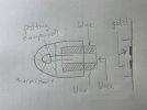
No. The leads go into the rubbery stuff. When you push the can onto the base, the rubbery stuff compresses a bit, presumably pressing against the gold contacts. The picture doesn't make any sense to me. Perhaps the magic smoke was in solid form and fell onto the ramp when I opened it up. Apologies to Teller and Ulam for the diagram.
gadget.jpg
 
Great question! PFM? I was hoping you'd say that the blue thing was OBVIOUSLY an Illudium Q-36 Conductive Electron Modulator...
 
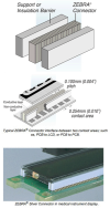
Are you familiar with the concept of zebra strips for liquid crystal displays?
It's a rubber strip with alternating conductive and insulatimg sections, connecting LCD glass to traces on the PCB.
1758495431456.png
It could be a finer pitch version of that.
 
That must be it, and explains everything. Thank you!
 
Why not just fill the whole can with potting compound and run the wires out?
...
I figured the rubbery material was for vibration isolation/thermal expansion...
I heard back from Insight. It is indeed an elastomeric connector. Why? Thermal isolation.
 
The blue is the insulator and the black is the stack of alternating insulator/conductor layers. Now that I know what to look for, I might need to get it under a microscope. The pins connect to the gold contacts through the stack, edgewise.

Imagine a deck of playing cards, except where the cards alternate between insulators and conductors. Now, stick a nail into the end of the deck; it's going to touch at least one conductive card, maybe a few, but not too many...

GeorgeC,
are we not pins?
 
Do you have a sticker on your car that says "I'm not driving fast, I'm just flying low"?
 
Closing the loop: I got a field test document from Insight that said if you put the probe in series with a 3.3kΩ, you should get a 1V drop across the resistor when powered with a 9V. I went shopping in my box o' hoarding and found a NOS 5-pack of 2.2kΩ resistors from Radio Shack. If I worked the voltage divider math backwards correctly, that should give a 0.7V drop. I measured 0.64V. Close enough...
 
OR...
Put two 2.2k resistors in parallel (1.1k end result), and put that in series with another 2.2k. Now you have a 3.3k resistor.

Your math is correct, though. Also, that voltage drop will happen at a certain temperature, usually 25°C/77°F.
So your reading being lower means the overall resistance was higher, so it points to the actual temperature being lower.
 
Back
Top