NA: Home Telephone (POTS) Wiring Issue

wanttaja

En-Route
Joined
Jun 7, 2008
Messages
4,577
Location
Seattle
Display Name

Display name:
Ron Wanttaja
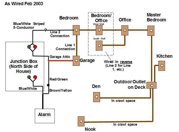
Our house was built ~25 years ago, many rooms have phone jacks.

About four years ago, we switched to a VOIP system, and Xfinity added a modem at the entry point that plugs into the existing wiring.

Recently, we started having some problem with static on the phone lines (we have two lines). At times, the lines would go completely dead. Other times, both worked just fine.

We had the service truck out, replaced the modem, but they said the phone problem was due to issues with the with the phone lines in the house. They pointed out that all the lights on the modem would flash when a phone in the house was taken off-hook. That, supposedly, meant there was a short in the line.

I agree that the issue is in the lines. If I plug a phone base station directly into the modem (disconnecting the house wiring) things work correctly and the lights don't start flashing.

However....I'm wracking my brains at what they describe as a "short" in the phone lines. When I use an ohmmeter on the house lines (disconnected from the modem), it doesn't show a short (all the phones inside are unplugged).

Also, as I mentioned, the modem lights all start flashing when a phone is taken off-hook. But why would it "short" when that happens...using several different phones? Why doesn't hanging up end the short (the lights don't stop flashing until the phone lines to the house is physically disconnected to the modem)?

Anybody got any good test techniques to chase down this wiring issue?

Ron Wanttaja
 
Phone line voltages are somewhat higher than your ohmmeter so it may see a short when it overcomes the resistance of the insulation. The usual suspects are moisture, bad connections or someone drove a staple through the line which is just showing up now. At 25 years they're probably wired in series so the trick is to take the jacks off the wall, figure out which line is upstream and downstream and start disconnecting to find the problem. Sometimes you'll find a mix of series and parallel so some jacks will have 3 or more lines, same idea, just start disconnecting to isolate the issue.
 
Mice love to chew phone line insulation. In our mountain cabin we finally resorted to plugging the base station of a cordless phone system (as well as the modem) as directly as possible into the tele trunk coming into the cabin. Other phones thereafter were cordless clones of the base station needing only chargers.
 
People still have hard-wired phones???
Yup. Not me, but my Mom does. She doesn't want to give it up. Has a prepaid cell phone she never uses but keeps adding minutes to it to keep them from expiring.
 
Here is what I would do. I have the same setup as you.

Disconnect all phones except one for now. Observe for several days.
If no problem with that one phone plugged in - plug in one other phone at a time at a new receptacle, waiting for several days between each to observe for anomalies. (only continue with each subsequent phone if nothing is noticed)
If a problem appears following the connection of any one phone, test that phone first. If it passes, then look at that receptacle.

If the problem occurs right away ie line #1 above, try a different phone on a different receptacle.

If none of this seems to trace it down, go back to the "junction box" (is it a punch block?) and disconnect either one at a time then test for disappearance of the problem or disconnect them all except one - test that for a while before reconnecting the other lines.

I had the same problem once - rain was getting into one receptacle. This would kill the entire system intermittently even though the rain had long ago stopped. I left that line disconnected at the punch block til it dried out and its fine now
 
I had a maddening problem with a patch cord in the box on the outside of the house once upon a time. It had corrosion in one of the connections.

I'd look for something similar in the outside box.

By the way, all the way until I found the problem, the phone company claimed the problem was on my side of the box. The patch cable was actually on their side.
Its always the customer's fault until proven otherwise. :)
 
Buy a four phone cordless system and plug the base station into the modem. Problem solved. :D
 
Buy a four phone cordless system and plug the base station into the modem. Problem solved. :D
Have that now. The problem is, the alarm system can't be hooked into it.

Ron Wanttaja
 
Yup. Not me, but my Mom does. She doesn't want to give it up. Has a prepaid cell phone she never uses but keeps adding minutes to it to keep them from expiring.

My grandmother also does this. The cell phone hasn't been charged in months. However, she'll buy a 100 minute card once a month and use her landline to activate them.
 
Here is what I would do. I have the same setup as you.

Disconnect all phones except one for now. Observe for several days.
If no problem with that one phone plugged in - plug in one other phone at a time at a new receptacle, waiting for several days between each to observe for anomalies. (only continue with each subsequent phone if nothing is noticed)
If a problem appears following the connection of any one phone, test that phone first. If it passes, then look at that receptacle.

If the problem occurs right away ie line #1 above, try a different phone on a different receptacle.

If none of this seems to trace it down, go back to the "junction box" (is it a punch block?) and disconnect either one at a time then test for disappearance of the problem or disconnect them all except one - test that for a while before reconnecting the other lines.

I had the same problem once - rain was getting into one receptacle. This would kill the entire system intermittently even though the rain had long ago stopped. I left that line disconnected at the punch block til it dried out and its fine now

This is the right way to do it... I’d start outside at the customer Demarc point and then test to each jack in the house with no phones connected anywhere.

But I saw this... so full-stop... different problem, different goals...

Have that now. The problem is, the alarm system can't be hooked into it.

Ron Wanttaja

If the alarm system is anywhere near the demarc point, I’d either test JUST the alarm System jack and disconnect all the others, or...

I’d just run a new cable to a jack just for the alarm system, if I was in a hurry and didn’t care at all about the house wiring... or...

Even faster, almost all houses are wired for at least two phone lines. Two pair of wires. If the problem is a wiring problem, just have the tech flip the POTS circuit over to “Line 2” and flip line 1 and 2 at the jack for the alarm. Let the alarm use the second pair and leave pair 1 dead.

Really though, and you may not be aware of this option... I’d just call the alarm company and get them to install a wireless device. There’s a number of them that even simulate POTS service to integrate older alarm systems and then use cellular data or commercial mesh RF networks to carry the alarm data to the monitoring facility.

Unless someone is paying for “continuous loop” monitoring, most criminals know to cut the phone line to the house outside and that they have anywhere from 15 minutes to 24 hours before the monitoring company even cares. (I chuckled at the scene in Breaking Bad at Gale’s house...)

The nice part about going with a cellular device is that the device can usually be installed inside where you’d have to set the alarm off to get to it and tamper with it. And the only way to really block it from working would be a broadband RF noise generator or similar jamming device.

Mine isn’t cellular, but it is a device that simulates dial tone, and modem connect for a GE panel, and actually goes out over a mesh commercial wireless network to get to the monitoring station. The panel has no idea it’s not making a phone call. The radio device simulates one for the panel and then sends the data out over a UHF transmitter.

Now back to the wiring. How old is the house?

Our old place was old enough it still had the carbon resistors used as fuses in line in the basement ceiling after the customer demarc, and a lightning strike cooked them (twice actually) and voltage and current would still pass through them but they were burnt internally and intermittently shorted to ground. Making noise. Had to cut into a ceiling to even find them. Wasn’t worth fixing them twice, either.

If nothing changed in the house wiring that was done by a human, a protection device is blown, a phone has gone bad, or a critter has chewed on a wire somewhere. Unplugging all phones and the alarm system ( eventually the alarm system does a “check in” and may also detect the RETURN of line voltage and report a phone line failure to the monitoring center when you plug it back in ) and testing to only the one jack that is needed ( even disconnecting the other jacks if needed ) will eliminate most of that. I have also RARELY seen a jack go bad, or a phone get jammed into a jack where the pins got mangled and touched, but closing the loop like that with a direct short would just take the line “off hook” permanently.

Note: Depending on the age of the house you may have loop wiring (phone line passes through all jacks in a big loop - sometimes with one loop per floor) or home-run wiring (each jack has its own cable from a central distribution point inside the house — much easier to troubleshoot).

Anyway, better options abound even for the alarm system. But, if you’re dead set on troubleshooting the wiring, just do it methodically. Unplug everything, test outside first, then work your way around, one jack at a time. If the house is loop wired, you can usually start at the jack closest to the demarc and see which way the cable behind the jack goes in the wall to figure out the direction of the loop and follow it around. Etc.

But if nobody cares about the other phones and you just want the alarm system working, I’d just fix that one jack, or change the technology used. Any good alarm company that’s been around long enough to have legacy systems will have options. Newer alarm companies will say they don’t and need to replace the system.
 
...Anybody got any good test techniques to chase down this wiring issue?
I had an issue a few years ago, don't remember the details. Our house is on one level with a basement, so I modified the phone wiring so that each jack was home-run to the demarc. I have a nice junction box from Radio Shack (RIP) with a bunch of RJ-11 jacks on it. It is plugged into the demarc. Each home-run wire plugs into its own jack. This makes it very easy to isolate a problem to just one phone or wire, just unplug 'em all and replug until the problem reappears.

It's a bit of a PITA to initially set it up; pay me now or pay me later.
 
Thanks much for all the advice. I was hoping for a simple test setup, but that looks like it's a no-go. The second line, the one the alarm is hooked to, is apparently operational, so I'll use a cordless on Line 1 until/unless I can figure out the problem.

Xfinity has offered to install new phone jacks for free, but not on interior walls. Hoping to NOT leave a dozen or so dead outlets.

Ron Wanttaja
 
Xfinity has offered to install new phone jacks for free, but not on interior walls. Hoping to NOT leave a dozen or so dead outlets.

Sounds like they want to do it in the usual cable TV way, run the wire around the outside of the house and drill through the walls. Which of course is ugly and a tremendously stupid way of doing things.

Of course, for both houses I bought I spent several weekends under the house and in the attic running conduit for all my cabling, so I may be biased.
 
Sounds like they want to do it in the usual cable TV way, run the wire around the outside of the house and drill through the walls. Which of course is ugly and a tremendously stupid way of doing things.
Yup. Not the way I want to do things. I'll pay someone to string new cable in the walls, rather than that.

Ron Wanttaja
 
A POTS line is a DC current loop; when you go "off hook" you are closing the loop. In the old days the network provided the power to the telephone set. Generically they were 48VDC open circuit, (that was gradually reduced in a lot of places to 12V); going off hook presented a few hundred ohms to the network, so its not a "short".
 
A POTS line is a DC current loop; when you go "off hook" you are closing the loop. In the old days the network provided the power to the telephone set. Generically they were 48VDC open circuit, (that was gradually reduced in a lot of places to 12V); going off hook presented a few hundred ohms to the network, so its not a "short".

Yup. But a short will still take it “off hook”. The loop is current limited.

And then there was also “ground start” that wasn’t a loop... but wasn’t used much in residential installs.

And then “4-wire” E&M...

You haven’t lived until you’ve manually adjusted the transmit/receive hybrids on 48 individual loop-start 2-wire lines on an analog conferencing bridge. Boy, there’s a good way to waste an entire day of your life just so some nice folks don’t have to listen to echo.

For extra fun, do it on a ladder in a 90F comm room ceiling near the air return at some small company in Tucson in the summer, or in a mold filled basement at a government nuclear weapons facility... after cleaning the mold and whatever else was growing in the thing out of the case from the window above leaking through it... after a call that it wasn’t working right... because the relays on the relay board were full of green/brown organic goo... no worries, they only lost 70 lbs of plutonium at the place, somewhere.

Yay telecom field engineering! :)

(In other words, no... I won’t troubleshoot anyone’s house wiring unless they’re making sure someone won’t die if a phone doesn’t work or they’re paying an awful lot. I’ve had enough telecom troubleshooting for a lifetime. LOL! But the moldy conference bridge at a multi-hundred million dollar Cold War facility was definitely a “treat”. Not. So glad they stuck mirrors under my Jeep to see if I was stealing anything on the way out, while they were losing/already lost/who knows, 70lbs of plutonium...)
 
Yup. But a short will still take it “off hook”. The loop is current limited.

The WAY it behaves badly is what throws me. I hook every thing up, pick up the phone, and get a dial tone. Hurrah!

Then I hang up and pick up the phone AGAIN, and there's no dial tone.

One happy bit of news...I vaguely recalled making some drawings of the routing of my house's telephone lines. A bit of digging found it (drawn in Canvas v 3.0, eighteen years ago). *Most* of the wiring is daisy-chained, which should be suitable for some of the diagnostic suggestions I've received.

The big re-discovery is that I have an outside jack on my deck. This will require a close look. The good news is that it's near the end of the daisy chain, so ensuring its continued operation isn't that big of a need.

Ron Wanttaja
 
Buy a cable tester at Micro Center, Fry's, etc. Disconnect all the lines at the main junction (usually right upstream of the NIB) and test them one by one for shorts, opens, or crossed wires.

Ten to one a mouse nibbled at the wiring.

Rich
 
What kind(s) of phones?
Three different kinds; one cordless system, two traditional-style corded types. Plus a handset with no ringer or dialing system (or hook...unplug to hang up).

Buy a cable tester at Micro Center, Fry's, etc. Disconnect all the lines at the main junction (usually right upstream of the NIB) and test them one by one for shorts, opens, or crossed wires.

The problem here is the failure sequence. Again, it works the first time. But it doesn't seem to break the connection when the phone hangs up. This doesn't seem to match the shorts/opened scenarios. Plus, I have two lines, both carried over the same four-conductor cable. The second line doesn't seem to have an issue, now. Thought it did before, but perhaps some of the work I did cleared that up, at least.

It was originally my intent to plug in a known resistance between the red and green wires at the entry point, and measure resistance at the various jacks.

Ron Wanttaja
 
Have that now. The problem is, the alarm system can't be hooked into it.

I think that's alarm company BS to get you to pay for their cell module (and subscription)

You could run 1 new wire from the alarm box to your demark and use it only for that.

The other "interesting" thing is alarm companies who "can't" use vonage or the like for the connection to base.

@denverpilot probably knows the reality of the telephony. I just think it's a money grab.

[Note: I do pay for cell module in my alarm system because... well... I don't know why]
With the cell module they company specifies the vocoder so that it is compatible with their system. Some VOIP systems let you set the vocoder so you have a chance of getting things to work. At least that's how I understand it. I've played around with settings to get fax machines to work on VOIP systems so I'm assuming it's the same for the alarm systems. I could be way off.
 
I think that's alarm company BS to get you to pay for their cell module (and subscription)
Alarm company isn't even aware of the current phone problems. I haven't asked if their system could be connected to a Panasonic cordless phone base station, but I can certainly believe that they don't want to interface to third-party non-standard hardware.

Their system works fine with the current VOIP. Believe it's connected to the second line, which is working fine now. They suggested a cell phone connection on the last service call, but I refused it.

Nextdoor neighbor had an attempted break-in a couple of years back. The perp's first step was to slash the phone lines to stop the alarm signal. Clever...but they apparently thought the HOUSE alarm required a phone connection. They kicked the front door down and ran when the siren went off.

Ron Wanttaja
 
@wanttaja - I bit the bullet and went cell module for the alarm system because if there were to be a fire I want trucks rolling and them to know my dog is in in the house (most likely in the master bedroom closet).

Steal most anything from me and I'll shrug and say "that's life." Mess with my doggie? Another story all together.
 
The problem here is the failure sequence. Again, it works the first time. But it doesn't seem to break the connection when the phone hangs up. This doesn't seem to match the shorts/opened scenarios.

First off, you’ve tested this with only one of those phones connected, right? And tested that the Voip device successfully goes on and off hook with a phone plugged right into it? If the device is bad, you’ll chase wiring for a week. Test from the delivery point outward until the problem is found. Disconnect as much as possible until you work your way further away from the demarc. Add things in as you get further away.

Anyway, your scenarios. Not open for sure, but shorts, especially weak ones, yes. The line in on-hook state has talk battery on it (nominally 48VDC but often much lower) and when the phone goes off hook it presents a low DC resistance (traditionally 600 ohms - carbon microphones) to the loop and current flows.

All it takes is 10mA to go off hook. On hook the phones should present a resistance in megaohms to the network. (They still have to detect AC ring voltage but generally the loop resistance is very high when on hook.)

Many cheap Voip devices just measure current flow with a current sense resistor and a micro controller to see if phones are on or off hook and aren’t very “smart” about real world older wiring and phones. Capacitance and leakage cause all sorts of trouble. Those microcontroller inputs also get blown by static electricity discharges in winter when folks shuffle to the phone and zap themselves on it. Especially old rotary phones where the metal tab to stop your finger when dialing was exposed and connected to the metal case of the phone.

And some of those current sense circuits have some hysteresis between off and on, so you go off hook and then hang up and present the gadget with a high resistance path that isn’t quite high enough resistance and it thinks you’re still off hook. Or there’s leakage inside a damaged phone. Or in my old house’s case, the carbon “fuses” Bell used to use as whole house lightning “protection” were doing all sorts of nasty things instead of opening like they were supposed to. (Placing conductive high resistance charcoal in line on both sides of the loop isn’t helpful. Ha.)

That could be caused by leakage in a bad cable that’s been gnawed on, a bad wall jack, or even just a deteriorating cable with bad insulation, or leakage back through one of the phones / fried resistor or leaky cap.

But... stop here for a sec. WHERE is the the cable Voip feeding the house? Outside at the demarc or inside at a jack? Reason I ask: Another common mistake cable installers make sometimes is plugging the Voip device into the house jack indoors and trusting that the telco disconnected the house at the pedestal. They’re SUPPOSED to disconnect the house from telecom at the demarc but if they don’t... now you have a long run of buried wire to a pedestal or an overhead drop from a pole that might be open, might be single side terminated, or might even still be getting tall battery from telecom with no Service attached to it. Not to mention if some telecom guy being “helpful” punches those down to ground in the pedestal (not supposed to do that, but it happens). Or the buried cable goes bad. Or fills with water. Etc. 200’ of buried cable to a wet pedestal would pass 10 mA. See where this is going? Make SURE the house is completely disconnected from telecom’s cabling at the demarc if feeding voltage from a Voip device plugged into a jack or distribution inside. Even just the stray capacitance and cross talk is a problem and the buried cable makes a great antenna for noise.

This doc has some decent info in it from a quick Google search. Max leakage current when on hook usually shouldn’t exceed 10mA for any reasonable AC or DC voltage or even the tests done in case 120VAC is crossed with one of the conductors on the telephone loop.

http://www.hermonlabs.com/products/innerData/pdf/Analog Telephony Overview.pdf

They show some of the limits in that doc, that could be reversed into other measurements of a house. The easiest test would be to unplug everything and feed the house with a current limited 48 volt power supply at 1A and measure current flow. If it’s higher than 10mA the house wiring has a problem somewhere. With no phones attached it should be an open. Attach a phone. If more than 10mA flows that phone is bad. Wash rinse repeat.

Old princess phones are notorious for being problematic. Especially ones with their own AC power supplies for dial lights. It’s all supposed to be isolated but the capacitors go bad, etc.

I would say if you can go off hook once and then can’t go on hook, leakage to ground somewhere is the problem. It’s allowing current to continue to flow from the Voip device and it thinks the phone hasn’t presented it a high resistance at DC to disconnect the call. Usually that high resistance when on hook is in the megaohms at DC.

The other problem could be that one of the phones when going on hook presents a short-duration dead short for some reason and the Voip device marks the loop as having drawn too much current. Phones should never present lower than a 600 ohm resistances off hook and megaohms of resistance at DC when on hook.
 
Personally if I were troubleshooting that I would also want to listen right at the Voip device with a “butt set” in high resistance mode. (In a butt set, the speaker stays active while the line is on-hook, allowing you to hear a little more of what’s going on. Say a phone in the loop is doing some goofy thing like flash hooks as other phones disconnect... you’d be able to hear that with practice. You get used to hearing what a “normal” phone line transitioning through states sounds like.) But it’s not something that’s 100% necessary. I’ve just found stuff by clipping in and listening before. I’d want to know if there’s a loud click coming from one phone (maybe not even the one used) at disconnect like a short happened.

A partially critter chewed cable can have strange characteristics. Not a direct short but enough “cross talk” between the mangled pairs that current will flow from one to the other in the pair with the trouble or even to the other pair, for example. Not enough to pull the line off hook but once off hook, maybe enough to stay above 0.5 mA at 48VDC into roughly a 2000 ohm circuit load. Some devices will still see that as an off hook.

Can also be just insulation failing somewhere for that low of a current.

For your idea... you already should have a fixed very high resistance inside the house. The phones. If they’re working right.

Disconnect the line at the demarc and and all the phones inside completely including the alarm System on line two. Measure the house loop resistance of both pairs. If the resistance of either loop is low you have a short or a leakage path to ground somewhere. Can also test the combinations between the pairs looking for crosstalk.

As Rich mentioned. A cheap “Ethernet” tester at a big box store that just checks continuity can also be used pretty effectively. Just make an adapter to an RJ-11/12 to RJ-45 and test the center four pins. If you know the voltage the little device uses you could even measure current and have more info with a multimeter if you made up what we used to call a “test buiscuit”. Just a surface mount wall jack with the lid taken off and the wiring disconnected and then wired up in such a way that a meter could be inserted in line for a current measurement or the connections re-made properly in the biscuit and voltage could be measured.

But starts simple. Make sure that stupid Voip device works with a known good cable directly to each phone set. Off and on hook. That’s way easier than chasing the whole house.

One other thing and it shouldn’t matter at all these days but... whenever pulling old jacks off of walls I always check that the polarity is correct for the loop all the way through. It shouldn’t matter. It’s a loop. But some phones are designed wrong and weird things happen when red and green are reversed to them. (In the 80s The usually problem was the TouchTone(TM) DTMF tone generator wouldn’t work. Button presses were met with little clicks. Reverse polarity and a dumb DC power design inside would mean no voltage to the chip. Usually a Mitel 8870.)
 
^^ broke that into two posts because I hit a Tapatalk bug.

Sorry that’s long. I can do all of that a lot faster than I can explain it! LOL.

Run around house, unplug everything, go to demarc, unplug that, go to Voip box, test with biscuit and one of the phones from the house after testing multiple on off hook cycles with butt set, go grab the rest of the phones and test them. THEN start testing individual drops. If there’s a distribution panel, disconnect everything and one at a time.

You see how fast that goes, depending on the house wiring. Doesn’t take long in real time but you have to keep moving.
 
Many thanks for all the good advice....I'm happy to report that I've restored full service.

To recap, I had found a schematic I'd drawn of the phone wiring about 14 years ago. It had some puzzling elements. The house was built with a daisy chain setup, with a sort of "Star" arrangement under the house in the crawl space (which has a 7-foot ceiling....)
telephone.jpg

There are obviously some weird elements in this, such as the SEPARATE wiring for the second line going to the upstairs bedroom...where it connects to the normal four-line wiring. The second line has been working fine; no issues.

For a troubleshooting aid, I connected a pair of clip leads to the red/black leads of two standard telephone plugs. A 1K ohm resistor was connected to the first one. I unplugged the VOIP modem from Line 1, and plugged in the test resistance. I went to the first outlet in the daisy chain...the one in the garage. It's kittycorner from the entry point, and the phone cable goes through the garage attic.

I used the second clip-lead adaptor to measure the 1K resistance at the jack, then disconnected both red wires. The resistance was used to verify which was the input signal. I left the wire going to the next stage of the daisy chain disconnected, and plugged the VOIP system back in.

Got dial tone, and the modem didn't show the "Shorted" light flashing.

On the rest of the daisy chain, my main suspect was the outdoor outlet on the deck. ~25 years out in the Seattle rains.

Next step was to break the connection between the master bedroom and the deck.

At the phone outlet in the master bedroom, I plugged in an ohmmeter to verify the 1K resistance, and then used the same process to differentiate between the signal input and the line going to the deck jack. Disconnected the deck jack, and the VOIP modem was still giving me shorted alarms (yes, I let it recover each time).

So it wasn't the deck outlet. My next suspect was the "Office" jack, as it has somewhat of a weird wiring. Repeated the process, and still had the shorting issue.

Went to the first bedroom outlet, which is the next one after the known good jack in the garage. Went through the process, and STILL had the shorting issue.

So...the problem is in the cable from the garage outlet to the bedroom/

As I mentioned, the second line goes to the same outlet via an entirely separate cable. This meant the red/green pair was connected, but the yellow-black pair on the garage-bedroom tel line wasn't used at all.

So I just disconnected the red/green, and connected the yellow/black instead. All connected, working properly.

Obviously, SOMEthing's going on with that cable. It's not impossible that the yellow-black pair will be eventually affected, but I'll burn that bridge when I come to it.

Again, thanks for all the great suggestions.

Ron Wanttaja
 
Is your ISP using DSL? It is still the only option in some areas.
 
I’m soooooo glad I never did residential or residential outside plant work @wanttaja — not that I didn’t find some god awful stupidity in business wiring closets — but looking at your diagram gives me only a case of the mild heebie-geebies.

Seen worse, but still... eww. Haha.

Looks like at some point in that house’s past someone wanted a second line in the office for work, maybe before the alarm was installed?

“5-conductor” is weird though. And you don’t seem much “Brown” in solid color residential. But it’s out there. (One old Elmer shared many years ago that he found a house once where Harry Homeowner ran a new jack with speaker wire... LOL... crosstalk much?)

5b621ef3fbe17cb0f740cd3ebad09f38.jpeg

The usual stuff for modular cables in non-solid color configuration. To do an RJ-11/12 you just do the 568A variety with only four conductors.

b8c58a44e655823099457723ea55738d.jpg

How to match up or splice solid color cable to the 568A standard.

Wonder if they really did it as three lines in that house back in the day. Two normal lines and then added the Alarm line third so it’s on the oddball color code. Just out of curiosity is line 2 in the office also wired to the Alarm line?
 
"Five Conductor" is what I wrote down for that separate cable in 2003; didn't check this time, though I think it was at least six. They did have that 568 color scheme.

Before using the yellow/black, I tried one of the unused pair in the 568, since there was an unused set of 568 in the garage outlet. Wasn't connected to the 568 cable in the bedroom.

I believe line two is used for the alarm, as well.

Ron Wanttaja
 
By the way we had a company owned building once that all of the closets and riser cabling was done 568A and the horizontal stuff to the desks was done 568B. That’ll drive you bat-**** crazy...

Building was a former AT&T building and then the engineer wanted all the cabling standardized between the three Call Center buildings out at the operator workstations, so the workstations had to be the same for the traveling techs who might go from building to building.

The other two buildings were 568B throughout.

I used to get pages or phone calls from the guys who worked the two standard buildings about the time they started yelling and cursing loudly enough to be heard from inside the wiring closets and all the way down the hall... “WtF is up with this wiring at the 66-blocks?!”

Even better? The first install tech for the first fifty or so operator stations was red/green colorblind. We nicknamed him “wirehead”.

I guess it’s better than being nicknamed “sparky”. The poor guy who got that nickname blew up all sorts of things in -48 VDC power plants, and EVERY time we investigated, NONE of them were his fault, all manufacturing defects, but the nickname stuck. He was always mad about that.

He retired a number of years ago. I hope he’s enjoying his beloved golf somewhere. Guy taught me a ton, and was always the “wary” one when folks started messing with power. He’d tell them to test everything before throwing the breaker or pushing that fuse holder in, lest they release the magic smoke. :)
 
I've seen a lot of Red/Green Yellow/Black in residential but I never saw any with the White/Blue 3rd pair. Hmm.

As a side note, if you're sitting down in the ditch you just dug reconnecting the 2 pair phone cable you cut because it was buried 1-freakin' inch deep and somebody calls in, that 50Hz ringing voltage will really rattle you. Just in case you were wondering.

John
 
Wonder if they really did it as three lines in that house back in the day.
Actually, you might be on to something. I think the alarm was originally built into the house, but a couple of rooms have electrical boxes at light-switch height but covered with blank panels (e.g., no switches, outlets, etc.). They may well be end points for the 568A run.

Ron Wanttaja
 
As a side note, if you're sitting down in the ditch you just dug reconnecting the 2 pair phone cable you cut because it was buried 1-freakin' inch deep and somebody calls in, that 50Hz ringing voltage will really rattle you. Just in case you were wondering.

ROFL!

I showed a tech how to find a ringing line on a 66-block once by licking a finger and then QUICKLY running your finger down the exposed metal clips in the center of the block... but you want to be quick and it does bite a little. :)

And of course you’ll feel nothing if you go past the ringing line during the off cycle of the ring cadence. So you get to play Russian Roulette a couple of times.

And of course keep your other hand in your pocket so as not to tempt fate too much. Who knows what some idiot punched down onto all those pairs somewhere else. I’ve never seen 120VAC but friends have. That’ll give you a good buzz and make you want to kill whoever did it.

And of course wondering if anyone else has licked the 66-block via finger proxy before and you’re sharing whatever they left behind last year. LOL.
 
Back
Top