azure
Final Approach
Oakland-Troy KVLL.BTW, where in SE Mich. is the plane located?
Oakland-Troy KVLL.BTW, where in SE Mich. is the plane located?
I asked for arecommendation of an A&P with decent electrical troubleshooting skills on another webboard (BeechTalk) and two folks came up with John Johns (Avantgarde Aviation, PTK. 248-666-3730). I know nothing about him beyond the opinions I received. One additional recommendation was for Ralph at KAZO, someone I've also heard good things about from other sources.Oakland-Troy KVLL.
John is pretty sharp, with decades of experience. He was an FAA examiner for A&P's. He is not afraid to say "I don't know", and diagnoses problems with a systematic, methodical approach. I, obviously, trust him with my life!
Lance, is that 177RG at the flying club at Oakland Troy? If so, I know that plane well.
Anyway, I would echo Jon's recommendation that John Johns is probably one of the best in the immediate area. If the plane can be flown, then I suspect Ralph at Kalamazoo Aircraft (south central MI) might be even better suited.
I used to own a C172RG in my flight school fleet. The split battery master-alternator switch can cause weird problems in the charging system. If the mechanic hasn't already replaced it in his shot gun approach, he can add this item to a round of shot.
Also a very capable (but unfortunately distant) mechanic/pilot/instructor I know suggested taking a look at the master/alternator switch. The alternator output current does not flow though this switch but the field current does.
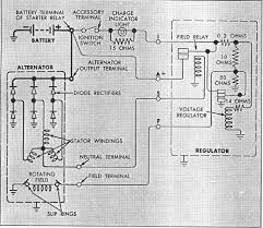
In the Cessna, the alternator side of the master only switches on a relay in the regulator, and that relay connects the A terminal to the voltage regulator component of the regulator assembly. Field current therefore comes from the A terminal (which runs back to the alternator output stud, which in turn is connected to the bus through the breaker) and is run through the regulator circuitry to the field.
This pic shows the setup as it's used in the automobile. The alternator's Stator terminal is used to activate the regulator; in the Cessna that S terminal is connected to the alternator side of the master switch. Note that the field gets its current not from the S terminal but from the A.
Dan
If that's the case in the Cessna, how does turning off the alternator switch stop the field current? It's my understanding that the ability to shut down the field current is a certification requirement.
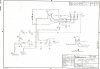
Obviously, I'm not too familiar with Cessna charging systems so I'm kinda in the dark here. Do you have a way to send an image of the Cessna wiring diagram, preferably one for a 14v C177RG?
I'm also noticing that the regulator in your Ford diagram is controlling the field current based on the voltage at the stator "wye" (center common) connection. I know that's typical of automotive regulators but I didn't think that charging systems in airplanes were set up that way. One relative issue is that the voltage on that (aux or stator) terminal is a little bit more than 1/√3 times the alternator output due to the way three phase voltages add and the drop across one diode vs two. Obviously an aircraft regulator that was intended to sense the higher voltage on the main bus or BAT terminal would have a much higher setpoint than one that's applicable to your Ford diagram.In the Cessna, the alternator side of the master only switches on a relay in the regulator, and that relay connects the A terminal to the voltage regulator component of the regulator assembly. Field current therefore comes from the A terminal (which runs back to the alternator output stud, which in turn is connected to the bus through the breaker) and is run through the regulator circuitry to the field.
This pic shows the setup as it's used in the automobile. The alternator's Stator terminal is used to activate the regulator; in the Cessna that S terminal is connected to the alternator side of the master switch. Note that the field gets its current not from the S terminal but from the A.
Dan
I'm also noticing that the regulator in your Ford diagram is controlling the field current based on the voltage at the stator "wye" (center common) connection. I know that's typical of automotive regulators but I didn't think that charging systems in airplanes were set up that way. One relative issue is that the voltage on that (aux or stator) terminal is a little bit more than 1/√3 times the alternator output due to the way three phase voltages add and the drop across one diode vs two. Obviously an aircraft regulator that was intended to sense the higher voltage on the main bus or BAT terminal would have a much higher setpoint than one that's applicable to your Ford diagram.
OK, I see that now, the Ford diagram was a bit fuzzy and I got my wires crossed. I would have sworn the S terminal connected to the coil of the relay controlling the field voltage until you stated otherwise and I looked again.The relay that the S terminal controls is just a shutoff. It's not the regulator relay; that's the other relay in the pic I posted earlier.
Thanks. I wasn't even aware that there was an indicator lamp in the circuit. I assume that a solid state regulator behaves in a similar fashion to the mechanical one in the Ford diagram (i.e. it must offer a sufficiently low resistance path to ground for the indicator lamp when the alternator is offline and the S lead must open the path from the alternator output when the voltage on that terminal is below some threshold). Given all that I would say that if the alternator switch was causing the latest problem the result would be insufficient voltage on the field.In the diagram, number 9 is the overvolt sensor. It goes in the line from the alternator switch to the S terminal and interrupts the flow if an overvoltage condition occurs. Interrupting that flow shuts the regulator relay off. Number 16 is the overvolt/low volt light and is driven by the indicator terminal of the regulator. Dan
One thing the diagrams make clear, though, is that in a Zeftronics "Type B" charging system, there is no way for the regulator to adjust the alternator output for changes in load if there is resistance between the BAT terminal and the bus, since all it does is sense the alternator output voltage directly at terminal "A". As long as the wire between the two is good, the VR is insensitive to load as long as the alternator is not overtaxed. To confirm that the variation I see in bus voltage is due to resistive loss, though, I'd really like to measure the BAT terminal voltage directly under load, like we did with the T&W alternator.
A good CO detector (with the ability to read well below 50 ppm) would provide that objective opinion. Perhaps you could borrow one from a fellow pilot. Just be aware that most CO detectors lose sensitivity with age.My mechanic fixed the induction leak and now something I'd noticed a couple of flights ago has gone back to normal: I'd started seeing EGT spreads of >100 between the cylinders at idle, now it's 60 at most. The exhaust leak is still eluding us and as of tonight I'm not even sure it's real. I ran the engine up to verify the EGT improvements, didn't notice any exhaust smell, so took it around the patch to get night current. I noticed nothing abnormal (the previous 177RG I flew also had a slight exhaust smell after the gear are lowered in the pattern) and now I'm wondering if my nervous system was just in an oversensitive state that day. I need to get an objective opinion.
One thing the diagrams make clear, though, is that in a Zeftronics "Type B" charging system, there is no way for the regulator to adjust the alternator output for changes in load if there is resistance between the BAT terminal and the bus, since all it does is sense the alternator output voltage directly at terminal "A". As long as the wire between the two is good, the VR is insensitive to load as long as the alternator is not overtaxed. To confirm that the variation I see in bus voltage is due to resistive loss, though, I'd really like to measure the BAT terminal voltage directly under load, like we did with the T&W alternator.
My mechanic fixed the induction leak and now something I'd noticed a couple of flights ago has gone back to normal: I'd started seeing EGT spreads of >100 between the cylinders at idle, now it's 60 at most. The exhaust leak is still eluding us and as of tonight I'm not even sure it's real. I ran the engine up to verify the EGT improvements, didn't notice any exhaust smell, so took it around the patch to get night current. I noticed nothing abnormal (the previous 177RG I flew also had a slight exhaust smell after the gear are lowered in the pattern) and now I'm wondering if my nervous system was just in an oversensitive state that day. I need to get an objective opinion.
My thoughts exactly! I ordered the Aeromedix model this morning.A good CO detector (with the ability to read well below 50 ppm) would provide that objective opinion.
That sounds like something I'd do but I didn't want to suggest it because of the potential for a short and subsequent flash melting of the added wire. At least by using a much smaller gauge wire than the existing lead from the regulator to the alternator you'd eliminate the possibility of damaging the existing wire if you did get a short. If you're careful this is OK but if you're not...Pull the wide plug off the regulator, take a foot or so of 22 or 24 gauge wire, strip both ends and stick one end into the "A" spade clip of the plug and reinstall it. Connect the voltmeter to the other end. Now you have a close idea of the alternator's A output.
Yeah, that's what I was thinking of trying, but didn't know if there would be enough space still to plug it back in with the wire sticking out of it.Pull the wide plug off the regulator, take a foot or so of 22 or 24 gauge wire, strip both ends and stick one end into the "A" spade clip of the plug and reinstall it. Connect the voltmeter to the other end. Now you have a close idea of the alternator's A output.
I think he would have said so if he'd done that. In short, I don't think he has really done anything worthwhile in looking for the leak. But since I noticed nothing last night, and he didn't either today though he taxied it for >20 minutes, it's possible he got some residue somewhere the airflow picks up when the gear are down and caused a temporary stink. As I said in my last post, I'm getting a CO monitor, which should tell the story.That exhaust leak: Is the mechanic taking off the heat muff from the muffler, pressurizing the exhaust pipe with a vacuum cleaner's "blow" function, and spraying really soapy water over the muffler barrel? Hard to find small leaks otherwise.
No but the side weatherstrip definitely is (you can see daylight through it). I suggested to my mechanic that that could be the source of the leak and he just said he didn't think so, but he could replace the stripping to see if it fixes the leak. I'd want to be sure that's the source first.Or the bottom weatherstrip on the RH door is leaking.
Dan