Capt. Geoffrey Thorpe
Touchdown! Greaser!
- Joined
- Jun 7, 2008
- Messages
- 15,622
- Location
- DXO124009
- Display Name
Display name:
Light and Sporty Guy
My fuel tanks are in the wings behind the main spar and, as built, are covered by the wing fabric which means that any fuel tank maintenance involves dropping the wing (no big deal) and fabric repair (something of a pita). So, I figure that installing an aluminum panel over the tank would make my life easier. Of course, to mount the panel, I would be attaching about 9 nut plates to the main spar web for #8 screws in the most inboard bay of the wing.
Considering that installing a fire extinguisher bracket is a big deal, I thought I would give the experts a chance to explain how I am going to die when I do this - but just as a reminder, the aircraft is E-AB so the laws of physics are different than a type certificated aircraft.
[Strut braced wing, single bolt at wing root for main spar attach - much like yea olde Cessna 150. Spar has a constant cross section except for a doubler at the strut attach. ]
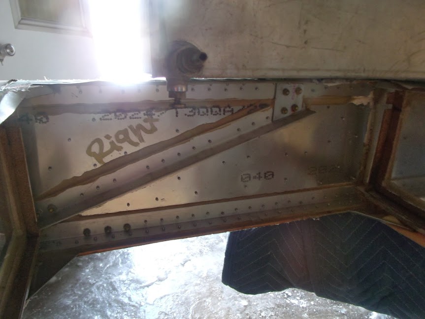
Fuel tank bay and main spar with the tank sitting on top. Wing root to the left.
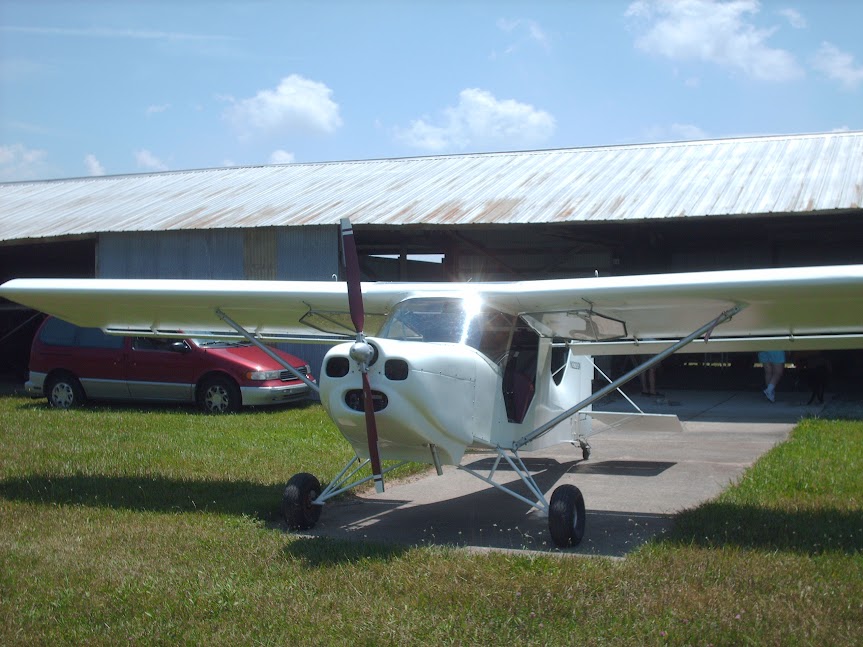
Da ride:
Considering that installing a fire extinguisher bracket is a big deal, I thought I would give the experts a chance to explain how I am going to die when I do this - but just as a reminder, the aircraft is E-AB so the laws of physics are different than a type certificated aircraft.
[Strut braced wing, single bolt at wing root for main spar attach - much like yea olde Cessna 150. Spar has a constant cross section except for a doubler at the strut attach. ]
Fuel tank bay and main spar with the tank sitting on top. Wing root to the left.
Da ride: