Does anyone understand bridge rectifiers, relays for auto trim?

FORANE

En-Route
Joined
Mar 7, 2013
Messages
3,539
Location
TN
Display Name

Display name:
FORANE
I just installed a Trio Pro Pilot autopilot in the Lancair. The Pro Pilot will optionally tie into an elevator trim servo for automatic trim setting. Their manual here:
http://www.trioavionics.com/Pro Pilot Manual 3.8.pdf
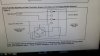
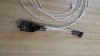
has the schematic for wiring the relay. The relay looks like the attached pic.

I don't understand how to wire this relay. I went to Radio Shack; they could not tell me how to wire this relay. Further, Radio Shack does not even have the Bridge Rectifier part number listed in the attached schematic.

I made my own harness for this Autopilot and coupled it to a Garmin 430W but do not understand how to make this relay.
Can anyone explain to me in a manner even a 2 year old could understand how to wire, or even what parts I need to make this work?
 

Attachments

  • 20141030_183601.jpg
    20141030_183601.jpg
    2.5 MB · Views: 158
You should be able to find a bridge rectifier and relay online or at a more sophisticated electronics store such as Fry's. I think these days Radio Shack mostly just wants to sell you a phone and even if they have what you want you'd probably have to buy it in a package that included two other items that you don't want or need.

The circuit itself is fairly simple. When you actuate your manual trim switch the polarity of the two wires to the motor will be either +/- or -/+ depending on which direction you want to trim. The rectifier will use that in either case to actuate the relay which will disconnect the auto-trim function and connect the manual trim function. Releasing the manual trim switch will cause it to revert back to the auto-trim mode.

You have another option to install an auto/manual toggle switch which would be simpler but would not provide any automatic override, you'd have to switch it to manual mode in order to utilize your trim control switch.
 
That's probably an old RS part number. They change them periodically. You should be able to find a substitute either at RS, another electronics store (like DigiKey or Mouser online), or if you need just one, on Amazon. You won't find it by part number - you'll need to find a substitute by specs.

Looking at the schematic, in the absence of specs, I'd probably use a 50 V bridge rectifier, 5 amps or better. That relay doesn't draw much current.
 
You will have a hard time finding a bridge rectifier that WON'T work...:yes:
Or you could just buy four diodes and wire as shown. RS might have those. The circuit is called a bridge rectifier. A part called a "bridge rectifier" is simply the four diodes in a common package. wsuffa's suggestion of 50v/5a would apply to individual diodes too.

Any of the bridge rectifiers here would probably work: http://electronics.mcmelectronics.com/search?cataf=&view=list&w=bridge+rectifier&x=0&y=0

You might find it handy to get one with push-on terminals so you don't have to fool with soldering. That style is designed for higher power so it will be overkill for you, but with (for example) the CM2504 at $1.52, who cares? MCM is fairly friendly to small orders, too. As mentioned, Mouser is another source as is Digi-Key.
 
ok so the relay wiring is pictured below:
$%28KGrHqFHJBsFInKS9zKZBSMPHo2Y5g%7E%7E60_57.JPG

What do I connect the pins to?
1 to Trio servo pin 5?
5 to manual trim drive?
9 to Trio servo pin 6?
13 to manual trim drive?
4 and 12 to trim motor?
8 and 14 to ?????


attachment.php


A bridge rectifier has +/- and 2 AC contacts correct?
If I got the CM2504 it looks like:
3929888.jpg

Will it be marked with +/- AC?
Is the +/- connected to 13,14?
AC or other pins connected to manual trim drive? Does it matter which one?

Still lost...
 

Attachments

  • 275-206.JPG
    275-206.JPG
    196.6 KB · Views: 8
ok so the relay wiring is pictured below:

What do I connect the pins to?
1 to Trio servo pin 5?
5 to manual trim drive?
9 to Trio servo pin 6?
13 to manual trim drive?
4 and 12 to trim motor?
8 and 14 to ?????


A bridge rectifier has +/- and 2 AC contacts correct?
If I got the CM2504 it looks like:
3929888.jpg

Will it be marked with +/- AC?
Is the +/- connected to 13,14?
AC or other pins connected to manual trim drive? Does it matter which one?

Still lost...
Get the data sheet for whatever rectifier you buy.

It appears that the "AC" input pins on the bridge rectifier go to the manual trim motor drive wires - when you put power on the manual trim wires, it will switch the relay to switch the trim motor from the trio servo pins 5,6 to the manual trim inputs. The rectifier + and - outputs would go to 13,14 as you guessed. Doesn't matter which of the AC input wires get connected to the manual trim wires.

Relay pins 9 and 12 are the relay out - those go to the trim motor

Relay pins 1 and 4 are the normally closed connections that go to the Trio servo pins

Relay pins 5 and 8 are the normally open pins that get conected to the manual trim inputs.

For it to work correctly the pins 1, 5, 9 would go together to drive the motor one way, and 12, 4, 8 would switch the other side of the motor circuit.

But, I ain't no A&P, and the diagrams don't tell us which way trio servo pins 5 and 6 drive the motor and which motor wires get connected to them, etc.

The people at Radio Shack can sign you up for a new cell phone but they know nothing (or less) about electronics.
 
Well, the diagram they are giving you does not specify plus and minus wire connections, just connections of pairs of wires. This means that some experimentation will be needed.

On your relay:


  • 13 and 14 are the coil wires. These connect to the DC output pins of the bridge. Polarity may not matter. If the relay is marked + and _, connect accordingly, otherwise just connect the wires as you like.
  • 9 and 12 are the "poles." These connect to the trim motor. Polarity matters, but not here. We'll fix polarity below.
  • 4 and 1 are the "normally closed" contacts. These connect to your AP output wires, Trio pins (T)5 and (T)6. When the relay is not active, your AP outputs are connected to your trim motor via these contacts.
  • Pins 5 and 8 are the "normally open" contacts. These connect to your manual electric trim switch. When the relay is active, the "normally closed" contacts open up and these "normally open" contacts close, connecting the MET switch to the trim motor.
  • The way that the relay becomes active is that it senses (via the bridge) that there is voltage on the MET wires. This causes the relay to become active, aka "to pull in."

So now lets talk about polarity:

As Silvair said, it is the voltage polarity from the AP or the MET switch that determines which way the trim motor spins. Since your diagram is unhelpfully silent on polarity, here is what you do:


  • After hooking everything up, AP off, use the MET switch to pull in the relay and run the trim motor. There is a small but not zero chance that your first try at connecting to the coil wires will not cause the relay to pull in when the MET switch is activated. If that is the case, reverse those wires and that should fix the problem.
  • If the MET switch causes the motor to run in the desired direction then you are done. If not, reverse the wires connected to pins 5 and 8. This should fix the problem.
  • Now try the AP (on the ground!). If the trim motor spins the way the AP wants it to, you are done. If not, reverse the wires on pins 4 and 1. This should fix the problem.

Yes, the bridge should be market "AC" (x2), "+", and "-". (Depending on the relay, the bridge may not even be necessary but for now ignore that possibility.)

Guys, please check me over on this. I think I have it right, but there is the potential for brain fade and/or typos.
 
What do I connect the pins to?
1 to Trio servo pin 5?
5 to manual trim drive?
9 to Trio servo pin 6?
13 to manual trim drive?
4 and 12 to trim motor?
8 and 14 to ?????

A bridge rectifier has +/- and 2 AC contacts correct?

Will it be marked with +/- AC?
Is the +/- connected to 13,14?
AC or other pins connected to manual trim drive? Does it matter which one?

Still lost...

From the sounds of it this might be a bit over your head but here goes anyway:

1 and 4 will connect to Trio Servo pins 5 and 6
9 and 12 to the trim motor
5 and 8 to manual trim switch and to inputs of rectifier
13 and 14 to output from rectifier

You'll have to correlate the trim motor connections on 9 and 12 to both the Tipo servo and the manual trim switch to ensure the trim motor operates in the proper direction when commanded. You'll have to have at least a very basic understanding of diodes to figure out how to connect the rectifier, you are not using it to rectify AC, in this case it is only being used to provide the same polarity to the relay coil regardless of which position you place the manual control switch in.
 
These last few posts are exactly what I needed to read. Thanks guys.
 
I also agree with airdale that, in the case of the components you have it doesn't appear necessary to have the rectifier. The relay coil will pull the contacts in regardless of the polarity of the DC voltage applied.
 
I also agree with airdale that, in the case of the components you have it doesn't appear necessary to have the rectifier. The relay coil will pull the contacts in regardless of the polarity of the DC voltage applied.
I would suspect that the rectifier is there to provide a path for the flyback current when the coil is de-energized.
 
I would suspect that the rectifier is there to provide a path for the flyback current when the coil is de-energized.
Agreed, but since the relay coil is connected to nothing except a mechanical switch I don't know that the collapsing field has anything that it can damage. But that's why I didn't suggest that it be removed.

Nice to see that all three of us agree on the pin numbers! Comforting ...
 
Looking at the schematic, in the absence of specs, I'd probably use a 50 V bridge rectifier, 5 amps or better. That relay doesn't draw much current.

Why in the world would you use a 5 amp bridge? A 1 amp bridge is 90% overkill, but that's about the lowest value commonly available. For that matter, with a coil that draws less than 100 mA even a discrete bridge made out of 1N4148s should work.

But wait a minnit, let me go back and look at the circuit (the image is WAY big, by the way).

Be right back.

Jim

****************

Back. The bridge is necessary because the power supply input voltage can be either polarity coming off of trim motor drive can be either +/- or -/+. Now we all know that relays are nothing more than electromagnets and it doesn't matter which way we jam current through them. Bottom line is that the person drawing the circuit probably doesn't understand sparky as well as understanding wrenching.

I don't think that they are there to suppress the flyback effect. Shouldn't be a problem with a 75 mil relay.

Bottom line ... bridge rectifier not necessary at all. Bridge rectifier can be four simple switching diodes instead of a prepackaged device (at about a tenth of the cost. Bridge rectifier can be any current rating you like in excess of 0.1 amp; 1 amp is the "standard" size. How about I redraw the circuit for you showing these options?

Thanks,

Jim
 
Last edited:
Yea, that's probably the reason but I had noticed in the diagram from the manual that they had polarity signs on the relay coil. Regardless, we're talking about a three dollar component so may as well incorporate it as depicted.
 
... How about I redraw the circuit for you showing these options? ...
With respect, I would suggest that in this case better is the enemy of good. Shipping will cost far more than a klunky, wild-overkill, bridge with push-on terminals. It will also eliminate the hassle of figuring out how to wire, insulate, and mount four much more fragile diodes. So why optimize at the risk of confusion?
 
Last edited:
With respect, I would suggest that in this case better is the enemy of good. Shipping will cost far more than a klunky, wile-overkill, bridge with push-on terminals. It will also eliminate the hassle of figuring out how to wire, insulate, and mount four much more fragile diodes. So why optimize at the risk of confusion?
I do like the all in one prepackaged push on terminal box even if it is a little larger and possibly slightly heavier than could be done.
 
Jim, I am guessing this "is" is a typo.

I would be interested in seeing a simpler diagram, thank you.

The "is" is NOT a typo *IF* you want to maintain the polarity on the relay that Rat Shack shows. As I said, if I get the chance today I'll redraw the circuit showing the three options I mentioned. One of the options is WITHOUT the "is".

Jim
 
Success!

I built an auto trim relay today and test flew it. It works perfectly.
I owe a big thank you to you guys, Geoffrey, Dale, Silvaire, Jim...
If we ever meet I will give you a Lancair ride and a buy you a beer.

I used the Radio Shack relay 275-0206 and the Radio Shack Bridge Rectifier 276-1173.
Here is a pic of the one I made:
 

Attachments

  • 20141103_125006.jpg
    20141103_125006.jpg
    1.1 MB · Views: 21
Success! ... Here is a pic of the one I made:
Nice work! Be sure to mechanically support that bridge somehow. Those solid wires are intended to be soldered into a circuit board and never flexed. They will take some flexing as you hooked them up no problem, but will not like flexing/vibration on a long-term basis. Probably you already know this.
 
Good work. The "schematic" in your manual was sorely lacking, it's nice you got some help.

I had to look at it for a couple of minutes to figure out what the intended function was.
 
Success!

I built an auto trim relay today and test flew it. It works perfectly.
I owe a big thank you to you guys, Geoffrey, Dale, Silvaire, Jim...
If we ever meet I will give you a Lancair ride and a buy you a beer.

I used the Radio Shack relay 275-0206 and the Radio Shack Bridge Rectifier 276-1173.
Here is a pic of the one I made:

Glad it worked for you. I'll not bother with the schematics if you've got a working model.

Happy dance ...

Jim
 
Back
Top