
DC Electrical Question

AK737pilot

Pre-takeoff checklist
Joined
Aug 20, 2017
Messages
147
Location
Wasilla, AK
Display Name
Chris
Home Airfield
Wolf Lake (4AK6)
I don’t want to get into a “is this legal?” debate, I just need a little “will this work?” advice (I am an A&P and will be responsible for all sign-offs).

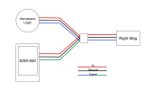
On my Cessna 182, I have an Aerospace Logic Tachometer gauge with a halls effect sensor on the right mag and a JPI EDM-830 with a halls effect sensor on the left mag.
My left mag is on the fritz and I’ve decided to replace it with a Surefly Mag which won’t support a halls effect sensor.

My idea is to use the Aerospace Logic sensor and splice the JPI wires into it:
1749917385175.png
I’m wondering if connecting both 5v wires into the one sensor will create problems, or just attach one of the power wires and splice just the signal wires?

It’s not really necessary to have the RPM indicated on the JPI, but I’d still like to make it work for data logging…
 
Why? Connect the 5V from ONE of the two devices to the mag sensor. Connect up the three groupnds and the three signal lines.
 
if you use two 5v sources one will always be higher and see the other source as a load. A diode on each leg isn't a real option as they also have breakdown tolerances. Your best bet would be to pick one source, or rig up a two transistors that would bias with the highest voltage.
 
A diode on each leg isn't a real option as they also have breakdown tolerances.
Big avionics manufacturers have no problem using diodes to feed critical pieces of equipment from multiple DC busses.
While the standard 0.5-0.7V drop of a regular PN junction diode could be a bit of an issue when the total voltage is this low (5V), Schottky diodes will only drop 0.2V or so. And the goal is not to balance the load, but to ensure that one source doesn't backfeed into the other, while still allowing proper operation of the other indicator in case one of the two indicators fails.
Your best bet would be to pick one source, or rig up a two transistors that would bias with the highest voltage.
Why use a single PN junction per leg when you could use multiple PN junctions and other components? Reliability? Never heard of her!
 
Big avionics manufacturers have no problem using diodes to feed critical pieces of equipment from multiple DC busses.
While the standard 0.5-0.7V drop of a regular PN junction diode could be a bit of an issue when the total voltage is this low (5V), Schottky diodes will only drop 0.2V or so. And the goal is not to balance the load, but to ensure that one source doesn't backfeed into the other, while still allowing proper operation of the other indicator in case one of the two indicators fails.

Why use a single PN junction per leg when you could use multiple PN junctions and other components? Reliability? Never heard of her!
We agree that the voltage can be an issue… something like 20%-ish could cause a problem. If all they are doing is exciting a coil (aka Hall effect sensor) it may of may not be an issue… that’s what the data sheet is for.

How you sense the voltage is up to you.. I’m just offering the idea. Maybe even an OP-AMP would be an easier/better solution as you’re really just looking for the spike. Just offering ideas. Since it’s an E/AB there are no limits. But simple/less parts is better.
 
Check the device manuals to see if the signal can be shared. Some sensors work on voltage differential and will result in erroneous indications. OAT sensor for example.
 
Check the device manuals to see if the signal can be shared. Some sensors work on voltage differential and will result in erroneous indications. OAT sensor for example.
This one doesn't. It's a hall effect sensor. It takes +5 and GND and puts a pulse out on the data line.

It's amusing to me that many of my probes are shared between my MVP50 and the predecessor JPI 830. The only one that isn't for some reason (and I don't think there's a technical reason) is the fuel flow.
 
Sharing 5 v line. It's entirely possible that it would do no damage. But there is no advantage to trying, so why risk it?

Sharing ground. Required. One ground to rule them all, one ground to find them. One ground to bring them all and to the voltage bind them.

Sharing hall sensor output: Likely to work. Depends on the input impedance (resistance) of the two devices and how much current the sensor can provide. I doubt that you will know for sure until you try. There is also a potential that it would work well under some conditions but not so hot so when temperatures rise.
 
I’ve got updates:

I connected the all power wires, ground wires, and signal wires respectively.
Fired it up and, what-do-you-know, both tach gauges work!
I don’t understand it, but I got to, cuz I was lookin right at it!

Next I should get that tachometer app on my iPhone and see if they match up.
 
Which tach app?
Does it sense vibration or light (prop)?
I don't know if there's an istuff version, but I used EngineRPM for Android. It uses the phone's microphone to listen to the exhaust sound; you have to tell it how many cylinders and whether it's 2 or 4-stroke.
 
I saw it posted somewhere else, it’s called Strobe Light Tachometer. Not sure how or if it works.
strobe tachs are wildly problematic. a prop spinning at 8000 and 16000 will still 'show'. if it's a PULSE tach then that's another animal.
 
strobe tachs are wildly problematic. a prop spinning at 8000 and 16000 will still 'show'. if it's a PULSE tach then that's another animal.
No light airplanes uses propeller RPMs like that.

The best tachs are the photo tachs, non-laser, as used by some model airplane enthusiasts. I found them as accurate as any "aircraft" tach checker. Just sit in the airplane, run the engine, and aim the thing at the prop. No reflective patch. There's usually a switch on the tach for two- or three-blade props. To calibrate the thing, hold it up close to a fluorescent light, on the two-blade setting, and it should read 3600 RPM, if the grid frequency is 60 Hz. Grid frequencies are tightly controlled, IIRC within .0033%. That's much more than close enough.

I have a laser tach, a real pain to use. You need a reflective patch on one prop blade, and then you have to get the laser spot on that patch as the engine is running at or near cruise RPM, with the airplane shaking and vibrating on the ground. Take your eye off the reflective patch to get a reading on the tach, and the laser drifts off the patch and the reading is gone.
 
Back
Top