Converting to Split Master switch

AK737pilot

Pre-takeoff checklist
Joined
Aug 20, 2017
Messages
147
Location
Wasilla, AK
Display Name
Chris
Home Airfield
Wolf Lake (4AK6)
Calling all A&P electrical wizards….

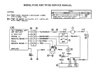
I’m converting my ‘68 Cessna 182 L from a single master switch to a split master as well as replacing the old voltage regulator with a Plane Power VR.

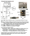
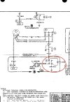
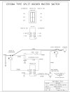
The Cessna service manual wiring diagram shows a diode between the ground and regulator pins on the master switch. I’m using a Stein Air wiring diagram as a guide and it doesn’t show the diode (I know this is just a generic diagram, thus the conundrum).

I’m sure I’m not the first to do this conversion…. Can someone chime in and tell me if I need to retain the diode on the new split master switch?
 

Attachments

  • IMG_1035.jpeg
    IMG_1035.jpeg
    521.7 KB · Views: 36
  • IMG_1037.jpeg
    IMG_1037.jpeg
    127.1 KB · Views: 38
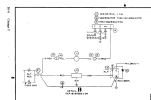
The Cessna R/TR 182s used an electronic regulator known as an Alternator Control Unit (ACU) similar to Plane Power's regulator, and they did not have a diode in the switch circuit. The service manual for those airplanes shows this:

1760117955489.png

Now, that wiring diagram from Stein shows no regulator of any sort, suggesting that the regulator is inside the alternator. Don't use that diagram for anything on your airplane.
 
Can someone chime in and tell me if I need to retain the diode on the new split master switch?
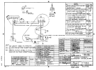
The Plane Power reg is a separate alteration from the switch and should be no issue. However, if you want to copy something, I'd copy the Cessna diagram when it went to a split switch which if I recall also had diodes as it is protecting from voltage spikes. There should be some free Cessna manuals online that will give you the different switch diagrams. Your only issue is if your mechanic considers it a major alteration which unfortunately some do.
 
Thanks guys, looks like I'll be retaining the diode.
I'm fortunate in that I am an A&P and have a good friend who is an IA that will be signing everything off (this is part of a larger re-wire/Dynon install).

Since posting here, I have indeed taken a good look at later service manuals with the split master switch as well as finding a great diagram and wiring description from Pinpoint Harnessing.
 

Attachments

  • Screenshot 2025-10-10 at 11.22.20 AM.png
    Screenshot 2025-10-10 at 11.22.20 AM.png
    1.4 MB · Views: 30
Thanks guys, looks like I'll be retaining the diode.
I'm fortunate in that I am an A&P and have a good friend who is an IA that will be signing everything off (this is part of a larger re-wire/Dynon install).

Since posting here, I have indeed taken a good look at later service manuals with the split master switch as well as finding a great diagram and wiring description from Pinpoint Harnessing.
If you are going to use that diagram and install that diode, you MUST also use the capacitor. If you don't, the regulator and alternator will be on all the time the master is on.

Edit: I was wrong there. I missed the ground connection between the diode and capacitor.

The capacitor may be there to reduce arcing at the switch contacts when switching off. Earlier airplanes had no such capacitor.
 
Last edited:
Ok, now I’m confused. The earlier single master switch shows just the diode between the power ground and the Field circuit. Then when Cessna split the master switch, the capacitor needs to be installed. What is the electrical logic of that capacitor? Why is it that just splitting the switch require the use of the capacitor? I’m not doubting it, I just want to learn…
1760198429851.png
1760198458093.png
 
Why is it that just splitting the switch require the use of the capacitor?
In general, a capacitor is used as an electrical shocker absorber to the voltage spikes managed by the diode. As to why, it could be as simple as the split switch has smaller contacts which need additional protection from those spikes. However, for a specific response a quick email to Cessna tech support will get you an answer.
 
As indicated in the drawing, the capacitor is a filter. The capacitor is likely used to shunt high frequency noise to ground. This helps eliminate this noise on the radio or being transmitted.

Rob
 
I haven't been keeping up with GA, but a few years ago I searched papers etc on voltage spikes in 12V aircraft systems, I found nothing on airplane systems but did find a paper from the 60's on 12V auto systems. From memory, the most significant voltage spike occurred if you disconnected the battery while the alternator was running. Based on that I assume that's why my old Grumman switch is ganged to always open both if the battery side is opened. Hopefully it kills the field side a little sooner IMO. I'm not sure what the specs on the Stein switch are but I'd make sure it works something like that.

As far as your diode question, and this is a half guess, it's a possibility the airplane's original voltage regulator contained 3 internal coils, each set up to open breaker points in series and in parallel for current regulation, voltage regulation, and reverse current flow. They used to teach those things in A&P school back in the 70's. If that's the case, maybe the diode and cap were to deal with field collapse in those coils. I doubt any modern aircraft voltage regulator would be constructed that way. If you don't have the original regulator installed, I would look in the mod paperwork that installed the VR to tell you what's needed.
 
Last edited:
As far as your diode question, and this is a half guess, it's a possibility the airplane's original voltage regulator contained 3 internal coils, each set up to open breaker points in series, parallel and for current regulation, voltage regulation, and reverse current flow. They used to teach those things in A&P school back in the 70's. If that's the case, maybe the diode and cap were to deal with field collapse in those coils. I doubt any modern aircraft voltage regulator would be constructed that way. If you don't have the original regulator installed, I would look in the mod paperwork that installed the VR to tell you what's needed.
That's more than half a guess. The only regulators with three relays were generator relays. Alternator relays never had more than two. The difference between generator and alternator relay function is pretty big, too. Alternators do not use current-limiting relays like generators did, and they don't need the reverse-current relay that the generator needed, since the alternator's rectifier diodes prevent reverse current flow. A generator regulator won't work for an alternator, and vice versa.
 
Back
Top