Cantilevered Wing

Mtns2Skies

Final Approach
Joined
Jul 12, 2008
Messages
5,622
Display Name

Display name:
Mtns2Skies
I understand how a cantilevered bridge works, but I can't picture how it works with an aircraft wing. Is it like the structure that can be seen in the cockpit of the citabria?
 
The wing spar typically is something like a cross section slab of wood or an aluminium or composit shape built up like an I beam shape. With positive Gs the top is in compression, the bottom is in tension, the web is loaded in shear.

You could build a truss style spar, but that is unusual.
 
no because a citabria is strut braced. there is only one bolt at the spar-fuselage attachment because the wing is hinged there. all the bending load is removed from the wing via the strut, only some of the lifting load is transferred into the fuselage.
 
"Another use of the cantilever is in fixed-wing aircraft design, pioneered by Hugo Junkers in 1915. Early aircraft wings typically bore their loads by using two (or more) wings in a biplane configuration braced with wires and struts. They were similar to truss bridges, having been developed by Octave Chanute, a railroad bridge engineer. The wings were braced with crossed wires so they would stay parallel, as well as front-to-back to resist twisting, running diagonally between adjacent strut anchorages. The cables and struts generated considerable drag, and there was constant experimentation on ways to eliminate them.
It was also desirable to build a monoplane aircraft, as the airflow around one wing negatively affects the other in a biplane's airframe design. Early monoplanes used either struts (as do some current light aircraft), or cables like the 1909 Bleriot XI (as do some modern home-built aircraft). The advantage in using struts or cables is a reduction in weight for a given strength, but with the penalty of additional drag.
This reduces maximum speed, and increases fuel consumption.
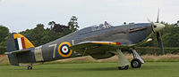
A British Hawker Hurricane from World War II with cantilever wings


Hugo Junkers endeavored to eliminate virtually all major external bracing members, only a dozen years after the Wright Brothers' initial flights, to decrease airframe drag in flight, with the result being the Junkers J 1 pioneering all-metal monoplane of late 1915, designed from the start with all-metal cantilever wing panels. About a year after the initial success of the Junkers J 1, Reinhold Platz of Fokker also achieved success with a cantilever-winged sesquiplane built instead with wooden materials, the Fokker V.1.
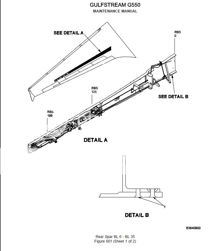
The most common current wing design is the cantilever. A single large beam, called the main spar, runs through the wing, typically nearer the leading edge at about 25 percent of the total chord. In flight, the wings generate lift, and the wing spars are designed to carry this load through the fuselage to the other wing. To resist fore and aft movement, the wing will usually be fitted with a second smaller drag-spar nearer the trailing edge, tied to the main spar with structural elements or a stressed skin. The wing must also resist twisting forces, done either by a monocoque "D" tube structure forming the leading edge, or by the aforementioned linking two spars in some form of box beam or lattice girder structure.
Cantilever wings require a much heavier spar than would otherwise be needed in cable-stayed designs. However, as the size of an aircraft increases, the additional weight penalty decreases. Eventually a line was crossed in the 1920s, and designs increasingly turned to the cantilever design. By the 1940s almost all larger aircraft used the cantilever exclusively, even on smaller surfaces such as the horizontal stabilizer, with the Messerschmitt Bf 109E of 1939-41 being one of the last World War II fighters in frontline service to have bracing struts for its stabilizer."
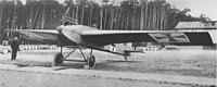

The pioneering Junkers J 1 all-metal monoplane of 1915, the first aircraft ever to fly with cantilever wings


Wikipedia is your friend.
 
Last edited:
I understand how a cantilevered bridge works, but I can't picture how it works with an aircraft wing. Is it like the structure that can be seen in the cockpit of the citabria?
The location of the spar carry-through can be seen in this interior photo of a Cessna Cardinal. Strut-braced Cessnas don't have to have the headroom-obstructing spar carry-through in the cabin.

That's why, by and large, high-wing light airplanes are strut braced, and low-wing airplanes are cantilever. In a low-wing, the spar carry-through can be placed out of the way under the seats (front seats in Bonanzas; back seats in Cherokees, Mooneys, etc.). In a high-wing, it can be tricky to locate the main spar (which is at the point of maximum thickness of the wing) so that it is out of the way of occupants' heads.

cessna_177b_1971_int.jpg


In the case of the Cardinal, that was accomplished by using a "laminar flow" airfoil with max thickness relatively far aft, and mounting that wing as far aft as possible. That succeeded in putting the spar carry-through comfortably behind the pilot's head, but it also made the airplane inherently nose-heavy. Thus it needed extra pitch control authority, which led to Cessna's first use of a stabilator, which in turn led to additional handling issues that had to be addressed in development and in the field.
 
If the wing has external bracing, it is not a cantilever design. If it has no external bracing, it is a cantilever design
 
I was just looking at a semi-disassembled 150 at the A&P school. As a retired civil engineer, I appreciated the strutted wing as basically a truss. In that type of wing, the carry-through member is mostly in simple compression and can be much smaller than it need be in a cantilever design. As previously mentioned, in a cantilever, the center (carry-through) section is carrying the highest bending moment and might be the tallest portion of the main spar depending on design but will be beefy in any case.
 
I understand how a cantilevered bridge works, but I can't picture how it works with an aircraft wing. Is it like the structure that can be seen in the cockpit of the citabria?

How do you understand a cantilevered bridge to work? I am trying to see why you cannot extend that understanding to a wing.

How does the below differ from a wing?

Cast-on-site_Cantilever_Bridge1.jpg
 
Last edited:
Think of the fuselage as a big rock sinking on a big plank of a wing.
 
How do you understand a cantilevered bridge to work? I am trying to see why you cannot extend that understanding to a wing.

How does the below differ from a wing?

Well I should rephrase... how does the spar differ in a cantilevered wing vs non. I know it is heavier but is that because it is simply beefed up and larger or is there an intricate structure around it to beef it up? And how does it attach all of that lifting force to the fuselage?
 
Last edited:
The location of the spar carry-through can be seen in this interior photo of a Cessna Cardinal.

cessna_177b_1971_int.jpg

Did all non-RG Cardinals comes with a third row seat? I've never seen that. Looks like an old picture. In the RG of course you couldn't do that because of the main gear well "bump".
 
Did all non-RG Cardinals comes with a third row seat? I've never seen that. Looks like an old picture. In the RG of course you couldn't do that because of the main gear well "bump".

Option for most of the 100 series planes
 
It looks so comfortable! :no: :rofl:
 
Well I should rephrase... how does the strut differ in a cantilevered wing vs non. I know it is heavier but is that because it is simply beefed up and larger or is there an intricate structure around it to beef it up? And how does it attach all of that lifting force to the fuselage?

The big thing with a cantilevered wing is the bending moment at the root of the wing. The forces there (a torque) are much higher than the actual force of lift. So, what typically is done is to have a structure that is similar (or heavier) than the wing spar that connects between the two wings to carry the bending load and the airplane hangs from that structure. One wing will create a bending load the attachment one way and the other the other way so you end up with a compression load in the top and a tension load in the bottom of the carry through structure. Typically an I beam type kind of shape is used.

Or, in some cases, you have a one piece wing where one spar goes through both wings and carries the bending loads in itself.
 
Did all non-RG Cardinals comes with a third row seat? I've never seen that. Looks like an old picture. In the RG of course you couldn't do that because of the main gear well "bump".
Child seats were optional on everything from C-150 through C-182 in those days. Though few child seats were sold, they were often shown in Cessna ads, such as this 1970 brochure.
 
Well I should rephrase... how does the strut differ in a cantilevered wing vs non. I know it is heavier but is that because it is simply beefed up and larger or is there an intricate structure around it to beef it up? And how does it attach all of that lifting force to the fuselage?

There is no strut in a cantilevered wing, there is a carry thru spar. A strut is external bracing.
 
Is that the same shape as the rest of the spar too?

Probably not and there is no reason it need be. The taller the spar, the lighter it can be to carry a given bending load (assuming an I-beam type design). The designers would have wanted to minimize the headroom lost due to the overhead carry-through spar so they would have sacrificed some weight (i.e. made the part heavier) to enable them to make a vertically shorter spar in the pax compartment. You can see in the pic that the spar is taller near cabin walls.

Further, they are "hanging" the weight of the fuselage where the pillars and wing spars connect at the outboard ends of the carry-through spar. In that case, the carry-through is not seeing much in the way of bending loads and is more of a compression member. (see my comments in the next reply.) The highest bending loads in a single member are immediately outboard of those attachment points (due to the "ring" structure taking some bending load off the carry-through) and we can expect the spar to be tallest there. It can decrease in height and weight as it continues outboard from there on each side of the airplane.
 
Last edited:
Here is the spar. As you can see, it gets shorter and narrower as it proceeds outward from the wing root. You can also see that the flange thickness and the web thickness is also decreasing. Now, since it attaches to the carry-through with two bolts, upper and lower, it will be transmitting the maximum bending moment to the attachment points. (as opposed to the main spar of the C-150 I was just looking at which cannot transmit bending load to the carry-through spar as it attaches with only one bolt and is a truss.) However, that bending moment will be handled by the entire structure that includes the carry-through spar on top, the pillars on either side (which look pretty sturdy), and whatever member joins the base of the pillars together (also probably sturdy). Basically, a ring, so that the overhead carry-through does not carry more than a fraction of the bending moment and so can be shorter in height in the center than the spar at wing root. IANAAE but I am a retired civil engineer.

177spar.jpg
 
Last edited:
My Jodel D-11, a wooden airplane, has a spar built up from spruce members and birch plywood skinning. It forms a long box to take all the lift, drag and torsion loads generated by the wing, and also carries the landing gear loads. Once it's built, it's one piece tip-to-tip. Very stout.

Halfway down this page, click on the cutaway:

http://www.jodel.com/index.asp?p=d11&themodels

Dan
 
Last edited:
The location of the spar carry-through can be seen in this interior photo of a Cessna Cardinal. . .

In a high-wing, it can be tricky to locate the main spar (which is at the point of maximum thickness of the wing) so that it is out of the way of occupants' heads.

cessna_177b_1971_int.jpg


In the case of the Cardinal, That succeeded in putting the spar carry-through comfortably behind the pilot's head. . .

Where it lies in relation to one's head depends on the height of the pilot/position of the seat. I am 6'4" or better, and I never moved the seat in my Cardinal from its aft-most position. The seat back was slightly reclined so that my head was actually behind the hump in the headliner. (I would duck my head slightly to lean forward to look ahead of the wing in a turn).

In my 210, my head is in front of the hump.

Wells
 
Imagine my surprise when I looked for the spar inside our Gulfstream G550's wing and could not find it!

The wing attach points are numerous, and substantial. With the 4 corner attach points being extra beefy. It looks like there are at least 20 of them!

Anyway, the wing is constructed with very thick skins, plenty of ribs and stringers, and substantial fasteners. There is a removable leading edge (heated) and a small bit of room for cables, wires and hydraulics on the rear beam.

The wing has a "rear beam" that is thin. The wing also has a "front beam" that is thin. Both of those are not classic spars. They are simply there to keep the fuel in!

But the bottom line is this: There is no internal, load carrying spar. The stress is fully located in the skins.

How's that for a "cantilevered wing".

Here is a view of the wing at 51,000 feet!

img1406o.jpg
 
Imagine my surprise when I looked for the spar inside our Gulfstream G550's wing and could not find it!

The wing attach points are numerous, and substantial. With the 4 corner attach points being extra beefy. It looks like there are at least 20 of them!

Anyway, the wing is constructed with very thick skins, plenty of ribs and stringers, and substantial fasteners. There is a removable leading edge (heated) and a small bit of room for cables, wires and hydraulics on the rear beam.

The wing has a "rear beam" that is thin. The wing also has a "front beam" that is thin. Both of those are not classic spars. They are simply there to keep the fuel in!

But the bottom line is this: There is no internal, load carrying spar. The stress is fully located in the skins.

How's that for a "cantilevered wing".

Neat. That would be a stressed skin or monocoque design. Used in cars since, when, the 1970's? Application to aircraft will become commonplace with advanced computers that can perform finite element analysis to minimize weight in complex load-bearing structures. I am sure that is already the case at Boeing and Airbus:

"FEM allows detailed visualization of where structures bend or twist, and indicates the distribution of stresses and displacements. FEM software provides a wide range of simulation options for controlling the complexity of both modeling and analysis of a system. Similarly, the desired level of accuracy required and associated computational time requirements can be managed simultaneously to address most engineering applications. FEM allows entire designs to be constructed, refined, and optimized before the design is manufactured."
 
The G550 maintenance manual calls them beams in one section and spars in another.

Capture35_zps266e3f8b.jpg
 
Last edited:
Neat. That would be a stressed skin or monocoque design. Used in cars since, when, the 1970's? Application to aircraft will become commonplace with advanced computers that can perform finite element analysis to minimize weight in complex load-bearing structures. I am sure that is already the case at Boeing and Airbus:

"

Not a new concept. The Lockheed Electras (all built between 1959 and '61) in our fleet have milled wing planks that form the skins and carry the compression and tension loads; the spars are there to keep the planks in the right relationship to each other and to act as fore and aft walls for the fuel compartments.

It's not known as monocoque construction, though. That term usually refers to a structure that uses ONLY the skin to carry loads, no other formers or ribs involved. Very few truly monocoque designs out there.

Dan

Fair enough. Semi-monocoque but often just called monocoque. At least that is what I have always heard such a structure termed in auto design (e.g. MB 190SL). Main point being that the skin is stressed to a marked degree more than aircraft with a heavy spar. IANAAE.

You have a fleet with Lockheed Electras?
 
Not a new concept. The Lockheed Electras (all built between 1959 and '61) in our fleet have milled wing planks that form the skins and carry the compression and tension loads; the spars are there to keep the planks in the right relationship to each other and to act as fore and aft walls for the fuel compartments.

Are these planks localized (i.e. running longitudinally top and bottom down the center of the wing) or is the entire wing surface, top and bottom, made of milled planks? Not important, found some more info on the web.

BTW, I was not implying that stressed skin is a new concept, I am saying that computerized finite element design will take it to a new level as regards weight savings. And probably has already.
 
Last edited:
All modern jets skins are milled sheet skins.

The Hawker series is a one piece top and one piece bottom skin bolted to the milled ribs and milled spars
 
Imagine my surprise when I looked for the spar inside our Gulfstream G550's wing and could not find it!

The wing attach points are numerous, and substantial. With the 4 corner attach points being extra beefy. It looks like there are at least 20 of them!

Anyway, the wing is constructed with very thick skins, plenty of ribs and stringers, and substantial fasteners. There is a removable leading edge (heated) and a small bit of room for cables, wires and hydraulics on the rear beam.

The wing has a "rear beam" that is thin. The wing also has a "front beam" that is thin. Both of those are not classic spars. They are simply there to keep the fuel in!

But the bottom line is this: There is no internal, load carrying spar. The stress is fully located in the skins.

How's that for a "cantilevered wing".

Here is a view of the wing at 51,000 feet!

img1406o.jpg


Nice pic....... I sometimes fly around at FL450 in a CJ but the extra 6000 feet does add to the view..:yes:;)..

Your wing is a "stessed skin" design.. Don't discount the load that the front and rear spar. (rear and front beam as you call them) is carrying...
 
no because a citabria is strut braced. there is only one bolt at the spar-fuselage attachment because the wing is hinged there. all the bending load is removed from the wing via the strut, only some of the lifting load is transferred into the fuselage.


Yeah but........... You have lifting loads imposed on the wing outboard of the strut attach point.... from the strut inboard,the spar in supported and is not really loaded that high at all... The section of the wing outboard of the strut, or the last 6 feet or so , is highly loaded during high G manuevers. IMHO.
 
Neat. That would be a stressed skin or monocoque design. Used in cars since, when, the 1970's? Application to aircraft will become commonplace with advanced computers that can perform finite element analysis to minimize weight in complex load-bearing structures. I am sure that is already the case at Boeing and Airbus:

I have a 1946 Luscombe that is built that way. There are only two ribs in the wing, one at the root and one at the lift strut attach point.
 
Yeah but........... You have lifting loads imposed on the wing outboard of the strut attach point.... from the strut inboard,the spar in supported and is not really loaded that high at all... The section of the wing outboard of the strut, or the last 6 feet or so , is highly loaded during high G manuevers. IMHO.

For that reason the Cessna propaganda calls my 182 a "semi cantilever"
 
Back
Top