After new engine install, loadmeter is pegs to the right

mr_happyland

Line Up and Wait
Joined
Nov 3, 2013
Messages
517
Location
Los Angeles
Display Name
mr_happyland
Home Airfield
KWHP
In my newly overhauled Grumman Tiger, the loadmeter pegs to the far right when increasing RPM above @ 800. It falls back to zero when power is lowered below that same amount. This Tiger has a 28v system and rather than an ammeter,has a loadmeter that performs as a voltmeter when pushing a button. The voltmeter readings is normal, but before the overhaul, the loadmeter would read around 1.0. My JPI 700 battery votlage reading also seems normal.

My IA told me that it's just a bad reading and that the electrical system of the AG5B's are notoriously fickle. He also mentioned something about the shunt likely sending a bad reading to the gauge. Posting here more others' opinions. I've attached a video that shows what the gauge does when increasing/decreasing power above 800 RPM. Thoughts?

View attachment IMG_6065_1.mp4
 
A load meter should (almost) never read 1.0, so something was wrong before the engine change as well.
 
It's a wiring issue, possibly a damaged uninsulated section of conductor going to ground due to airflow over the engine when the power is increased, thus pegging the gauge.
 
Is that load meter is normalized? Seems to go only to 1.25, presumably a dimensionless scalar.

Once there was a shunt, now it’s a short.
 
OR, as the mechanic said, the shunt is bad/has a loose connection.

THE PROBLEM: all the alternator current goes through the shunt. If it's not connected right, at a minimum your battery isn't being charged. Worst case, something is about to catch fire.
Have it sorted out before further flight.
 
He's one of the leading Grumman specialists so he knows these specific planes better than you or I. It's the only type he works on.

Ok, well maybe he knows his stuff and it got lost in translation.

But for the record, no electrical system is "fickle". They all obey Ohm's Law: V=IR. And that makes it possible to methodically and definitively troubleshoot an issue like yours.
 
Ok, well maybe he knows his stuff and it got lost in translation.

But for the record, no electrical system is "fickle". They all obey Ohm's Law: V=IR. And that makes it possible to methodically and definitively troubleshoot an issue like yours.
True, but they also obey Faraday’s laws, and intermittent mechanical “connection points” can make it difficult to diagnose certain types of failures.
 
The system may be fickle, but it will be no different than the systems used in other airplanes. Piper commonly used a loadmeter.

As some have said, and bad shunt could do it, but I would expect the pegging to happen any time the engine was running. With ammeters, the shunt is usually built into the meter housing, and the battery current passes through it in both directions, charging and discharging.

1756171830361.png

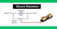
The meter itself is just a milliammeter. It takes very little current to peg it. It is reading the voltage drop across the shunt, which is a resistor with very little resistance but which can handle plenty of amperage, and that voltage varies directly with the amount of current passing through the shunt. Basically, the current looks for whatever path it can find, and a little of it goes through the meter movement and moves the needle.

Now, if that shunt's resistor bar is loose or corroding, the shunt's resistance goes up and more current goes through the meter and pegs it. But that shouldn't just start at a specific RPM.

The voltage regulator might be bad, sending full field current to the alternator for some reason as output voltage rises with RPM.

And, as other suggested, there might be a shorting alternator output cable, and the RPM sensitivity might be because the prop torque rotates the engine a bit and moves the cable. Since this problem arose after engine overhaul, I'd be looking at everything the mechanics had apart.
 
True, but they also obey Faraday’s laws, and intermittent mechanical “connection points” can make it difficult to diagnose certain types of failures.
They also obey Murphy's various Laws, just often enough to cost lots of money.

Murphy's Laws​

  1. If anything can go wrong, it will.
  2. If there is a possibility of several things going wrong, the one that will cause the most damage will be the first one to go wrong.
  3. If anything just cannot go wrong, it will anyway.
  4. If you perceive that there are four possible ways in which something can go wrong, and circumvent these, then a fifth way, unprepared for, will promptly develop.
  5. Left to themselves, things tend to go from bad to worse.
  6. If everything seems to be going well, you have obviously overlooked something.
  7. Nature always sides with the hidden flaw.
 
The OP said the meter can also read voltage, and the voltage is normal, He has a second voltage measurement that is normal.

IF the shunt was damaged, breaking some of the conductors, that would raise the resistance, and as Dan explained, that will increase the meter reading from actual. If the meter is connected in the output of the alternator, that rise will be with the increasing RPM increasing the alternator output.

Your POH will show where the shunt is located electrically, but not physically. It may be with the meter, as Dan said, or in front of the firewall, with two wires through the firewall to the meter.

Look in the engine space first, it is easier. Use your smart phone in video mode to scan the back of the meter if you have that capability. You will need good light there.

Good luck.
 
And DC ammeters only react to average DC current.. They care less about the nature of the load.
 
The system may be fickle, but it will be no different than the systems used in other airplanes. Piper commonly used a loadmeter.

As some have said, and bad shunt could do it, but I would expect the pegging to happen any time the engine was running. With ammeters, the shunt is usually built into the meter housing, and the battery current passes through it in both directions, charging and discharging.

View attachment 144477

The meter itself is just a milliammeter. It takes very little current to peg it. It is reading the voltage drop across the shunt, which is a resistor with very little resistance but which can handle plenty of amperage, and that voltage varies directly with the amount of current passing through the shunt. Basically, the current looks for whatever path it can find, and a little of it goes through the meter movement and moves the needle.

Now, if that shunt's resistor bar is loose or corroding, the shunt's resistance goes up and more current goes through the meter and pegs it. But that shouldn't just start at a specific RPM.
The voltage regulator might be bad, sending full field current to the alternator for some reason as output voltage rises with RPM.

And, as other suggested, there might be a shorting alternator output cable, and the RPM sensitivity might be because the prop torque rotates the engine a bit and moves the cable. Since this problem arose after engine overhaul, I'd be looking at everything the mechanics had apart.
Thanks for the detailed answer. Most everything firewall forward was removed during overhaul so my assumption has been something with the new wiring is the culprit. In your opinion does this sound more like an errant reading of the meter or something potentially more sinister?
 
all the alternator current goes through the shunt. If it's not connected right, at a minimum your battery isn't being charged. Worst case, something is about to catch fire.
I can tell you from experience (loaning my personally owned VOM to management) that the meter will go "poof" before it starts a fire.

But, yes, it is something that should be fixed. Step one would be to find a schematic of the electrical system.

OP says "battery voltage reading also seems normal" Define normal. Numbers at idle vs higher rpm - any change?
Internal or external shunt on the meter?
 
When I reinstalled my engine after overhaul, I did not use a jam wrench on the base nut when tightening the alternator field wire to the brush housing. The result was a cracked brush housing and intermittently functioning alternator.

I would start with the obvious: all direct connections to the engine and FWF.
 
Last edited:
Operating the engine with the meter pegged can ruin the meter. That will be a harder item to find than a shunt, they are somewhat generic. Replacing with a different brand but same rating should be no different than changing brand of spark plug.

Find the shunt, and follow the connections to the meter. Something is damaged or misconnected. Shunt forward of the firewall may have been damaged in engine removal, reinstall.
 
It's a wiring issue, possibly a damaged uninsulated section of conductor going to ground due to airflow over the engine when the power is increased, thus pegging the gauge.
Lots of things can happen when old wires are reused for these things.
 
Just a thought ...

Check the field wire to the alternator. If the conductor is broken at the connector INSIDE the insulation it will not be apparent from the outside. Can happen from vibration slowly work-hardening the conductor strands.

At rest enough of the conductor strands make contact. As the throttle advances, vibration and air flow stress the wire and the conductor separates.
 
In my newly overhauled Grumman Tiger, the loadmeter pegs to the far right when increasing RPM above @ 800. It falls back to zero when power is lowered below that same amount. This Tiger has a 28v system and rather than an ammeter,has a loadmeter that performs as a voltmeter when pushing a button. The voltmeter readings is normal, but before the overhaul, the loadmeter would read around 1.0. My JPI 700 battery votlage reading also seems normal.

My IA told me that it's just a bad reading and that the electrical system of the AG5B's are notoriously fickle. He also mentioned something about the shunt likely sending a bad reading to the gauge. Posting here more others' opinions. I've attached a video that shows what the gauge does when increasing/decreasing power above 800 RPM. Thoughts?

View attachment 144465

How does the loadmeter function? I am assuming it is somehow multiplying the current and voltage, but is that the total power draw, or power supplied by the alternator?
 
How does the loadmeter function? I am assuming it is somehow multiplying the current and voltage, but is that the total power draw, or power supplied by the alternator?

It works the same as an ammeter. It measures the voltage drop over a known resistor. Ohm's Law says current = voltage/ resistance, so the scale can be calibrated to display amps.

The difference is where the meter is placed. The ammeter is placed to measure current back and forth between the alternator and battery. The load meter measures current flowing from the alternator.

So the unit of measure is Amps (and not Watts)? The phrase "load" made me think it was different than a simple ammeter.
 
So the unit of measure is Amps (and not Watts)? The phrase "load" made me think it was different than a simple ammeter.
Just amperage. As the alternator's output voltage rises above the battery's voltage, current will flow from the alternator to the bus and from there to the battery. AS the battery recharges and its voltage matches the alternator's the current will stop flowing and the loadmeter will go to zero.

But if you turn on some loads, the battery's voltage falls and the alternator's output starts feeding both the battery and the loads and the loadmeter will show that.

The loadmeter won't show any negative figures because the diodes in the alternator prevent reverse flow.

An ammeter, being between the battery and bus, will show flow in either direction. It does not register the flow to the starter since the started current is huge and the ammeter and its shunt would have to be similarly robust. Its scale would make reading small amperages difficult. Starter current is taken off the master contactor's output terminal, bypassing the ammeter.

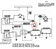
Below is a circuit from the PA-28 series. I found an AA-5B manual but it does not show a loadmeter circuit, just an typical ammeter circuit.
I have circled the loadmeter in red here; note that they call it an ammeter, but being in the alternator's output line makes it a loadmeter. It measure only the alternator's output.

1756314179325.png

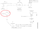
Now, an ammeter circuit, from a 172. Note that the ammeter is in the line between the battery and bus, and the alternator isn't even shown. The alternator's output is connected to the bus via a circuit breaker. As it raises the bus voltage, the battery will charge and the ammeter will show that. Shut off the alternator, or have it fail, and you will see a discharge on the ammeter as the battery takes the loads.


1756314547490.png

Note the alternator's connection to the bus, there. The breaker is called "Gen," a throwback to the generator.
 
Yes, and the reality is that “R” isn’t what really matters. “X” (impedance) is the key value, and “R” is only one component of “X”.
No, X is used to indicate the reactance, or opposition to AC current. Impedance is normally indicated with the letter Z. It is typically written as Z= R+jX. The j indicates it is a complex number, meaning that you cannot simply add the R to the X and get anything meaningful. Trigonometry is required. For the ammeter in a light airplane's DC electrical system the X is irrelevant/unknown and can be ignored, so Z=R.
 
Bell206 kindly sent me a link to the AG5B service manual and it has some good stuff in it. https://yankee-aviation.com/docs/AG5B Maintenance Supplement.pdf

Start reading at page 24-18, page 180 of the .pdf.

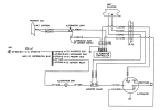
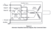
Most of the alternator wiring is straightforward, but this system has one thing I have never encountered elsewhere: an Aux terminal on the alternator that goes to an Aux wire on the ACU (alternator control unit, the modern version of a regulator). Now, that Aux terminal appears to be the same size as most of the other terminals on that alternator, including the two field terminals and a ground stud or two. Here's the schematic:

1756340739337.png

Note several things on that alternator: field 1 and field 2 are connections to the two brushes that feed field current from the regulator to the rotor (rotating field). One of them is grounded via a wire that goes to a ground stud, labelled EB27A18N, and the other goes to the ACU's blue wire via American's labelled wire EJ12B20 to EJ12A20. Those will be white wires with that number printed along them at intervals. The Aux terminal is connected to the ACU via EU41B20 to EU41A20 and to the white wire on the ACU.

The Aux, as far as I can find on internet searches, goes to the central wye connection in the alternator:

1756341176318.png

If it has the same function as the "S" terminal on the old, different alternators in cars, it was used to turn on the voltage regulator when the engine reached a certain RPM. In older airplanes, the S-terminal on the regulator is controlled by the ALT switch on the panel. Not sure that's what it's doing here, and my Cessna charging system manual never shows anything like it in any wiring diagram. This AG5B manual does not mention it in the system description. Lamar has several ACUs with the Aux function, but there is no info as to its purpose. For instance:

https://irp.cdn-website.com/d25e75f5/files/uploaded/73196636_(1).pdf

But, anyway, since the fault showed up on installation of the new engine, I suspect that a mechanic might have gotten some wires mixed up, like a field ground wire to the Aux terminal, or the Aux wire to a field terminal, or the Aux wire to a ground terminal, or something like that. Those wire identification markings are useful here.

The shunt is on the engine side of the firewall, above the battery.

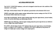
The ACU is on the aft side of the firewall, on the right side. It has lights on it for troubleshooting:

1756341729401.png

Aside from all that, the shunt and output cable should be examined for shorts or corrosion and so on.
 
Back
Top