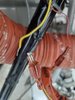
I'm not even sure if this is thermocouple wire, but does anyone know what type of connector/splice/terminal this is and where I can find another or a suitable substitute? The wire is very thin and is foe an EGT gauge.
Just trying to make life easy for my mechanic and source some parts. He said he "might" have a replacement but wasn't sure.
Thanks.
Just trying to make life easy for my mechanic and source some parts. He said he "might" have a replacement but wasn't sure.
Thanks.

")