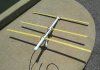
Well, the one on the left isn't fully deployed. Those elements that are pointing "up" should be more "down" than they are. Log periodic dipole array antenna, designed for some gain, but mostly wide bandwidth. The VHF television band covers two chunks of spectrum. 54 to 88 MHz (channels 2 through 6) and 174 to 216 MHz (channels 7 through 13). Looks like (without measuring) the elements that are folded are for channels 2 through 6 and the non-folded elements are for channels 7 through 13. Just a guess, but probably not too far off.
UHF television starts at 470 MHz (channel 14) and ends at 806 MHz (top of channel 69). Used to go higher as the channel numbers used to go beyond channel 80 (83?). That spectrum (806 MHz and up) has been given to other users (mobile phones, two way communications).
Interesting looking at the antenna on the right, it looks more like a Yagi-Uda array (AKA - Yagi). One driven element, one reflector and 3 directors. Typically designed for a narrow band of frequencies and some gain. I'd have to have a tape measure on the actual antenna to measure the element length (driven element) to see what frequency it was designed for.
The VHF/UHF/FM antenna was likely a log periodic dipole array with extra elements to work in the FM band (which starts at the top of TV channel 6 (88 MHz) and goes up to 108 MHz (bottom of aeronautical band)
I haven't used one of these antennas in decades. We've been on cable of one sort or another since late 1979. Oh, and yes, I'm guilty of being an amateur radio operator (Ham). Call sign is N6TPT.

Also 42 years experience as an EMC engineer, and antennas are an essential tool of the trade.