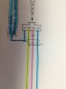
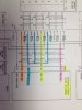
Wirinbg Diagram

Which diagram are you looking at Tim? Sometimes a T like shape is used for antenna. Most likely it is for id of a wire or cannon plug position.
 
Here is a picture of what I am asking about.
 

Attachments

  • photo.JPG
    photo.JPG
    9.9 KB · Views: 73
The dashed circle and ground is shielding- not sure what he T means. I think it means twisted wire.
 
I was thinking Twisted or the T. I also see a P pointing to two wires with a shield and assume that to be a single shielded pair.
 
Correct - Twisted
Typical twist rate is 2-3 turns per inch, and yes it is important.
 
So, with the following picture would this be three cables with a single pair of wire with their own shield or would a three pair cable with one shield be sufficient?

Also I note that there is no T, so does it hurt if they are twisted?
 

Attachments

  • photo.JPG
    photo.JPG
    50.8 KB · Views: 31
Learning is a great thing even at 56, now if I could only type "Wirinbg" thats pretty sad!!
 
Looks like a cannon plug setup. 3 sets of 2cable(shielded), but 37 is tied to all 3.
 
Those are some of the connections between the KI-202 and the KLN-89B. Twelve connections to the 202 and 14 to the 89B
 
If its called out for a twist then the twist is important for reducing noise caused by the varying lines of flux that emmit from a wire (left hand rule). Similar to how a magneto only on a much smaller scale and with changes of electrical intensity instead of a rotating permanent magnet causing the lines of flux to cut the other wire. This induces current that will picked up by the rcvr as noise and could possibly change the signal somewhat. Twisting has less inductance than parallel cables so in short, you should be fine as long as all of the grounds are in place.

Its been a while since i used that part of the old noggin...
 
Stresses my brain as well, last I used real electronics was in the Air Force. I still remember And gates, Nand gates, Or Gates, Nor gates, Flip Flops and Latches, single shots and the like. Most of the stuff I worked on didn't even have flat chips, most of it had IC Cans. Little 10 legged R2D2 looking devices.
 
Learning is a great thing even at 56, now if I could only type "Wirinbg" thats pretty sad!!

I suspect that I wasn't the only one who read "wiring" in the title....
 
Sometimes my tongue gets wrapped around my eye teeth and I cannot see what I am typing.
 
Sometimes my tongue gets wrapped around my eye teeth and I cannot see what I am typing.


Sometimes my hook smashes one finger of the 4.5 that remain and my tyging goejikul #%$$@#!!!
 
Stresses my brain as well, last I used real electronics was in the Air Force. I still remember And gates, Nand gates, Or Gates, Nor gates, Flip Flops and Latches, single shots and the like. Most of the stuff I worked on didn't even have flat chips, most of it had IC Cans. Little 10 legged R2D2 looking devices.

the stuff we were doing would make your head spin then!
 
Here is a pic I found of some of what I worked on. The CCU (Common Control Unit) used a ferrite core (ferrite doughnuts) that had read, write, sense, and erase wires running through them for local memory.

Interesting technology and a chore to maintain.

http://www.flickr.com/photos/gilwall/109018526/
 
So, with the following picture would this be three cables with a single pair of wire with their own shield or would a three pair cable with one shield be sufficient?

Also I note that there is no T, so does it hurt if they are twisted?

No. The individual grounded shield must be used around each pair(or triple). They cannot be bundled as one. This is to minimize or eliminate crosstalk between very low voltage signals on adjacent wires that could interfere.

Note that this circuit is going to drive either the NAV/RCVR or in the other switched position, to the left - the OBS. That big ganged switch between the Sperry unit directs the OBS SIN and COS(pins 35 and 36) values from the KLN 89B. Do not bundle these together, as they are phase shifted, and crosstalk may likely cause errors in the display unit. It has to be done just as you see it on the diagram.

It will not hurt if the wires are twisted. Most wire gauges used in avionics are twisted or stranded. Finding solid wire in this kind of installation will have a "NOTE: wire from xxx to yyy is MIL-SPEC blah blah" or some kind of wording on the chart near the bottom, or there will be another page with wire spec on it. In some cases, a solid wire is required, but this is quite rare.

Also, don't forget that the shield is grounded. Again, critical to insure there is no floating ground between the two chassis. Often, this is grounded to the metal case of the plug at the end of the cable.
 
That's a big b!tch :D lol I did a lot of micro-miniature circuit board repair. lots of surface mount components with lots if little legs.
 
This is what I used to use to design and setup hi speed circuits:

http://www.barrytech.com/tektronix/vintage/tek568.html

http://www.barrytech.com/tektronix/vintage/tek3s76.html

http://www.barrytech.com/tektronix/vintage/tek3t77a.html

http://www.barrytech.com/tektronix/vintage/tek230.html

The Tek 568 was the fastest, neatest thing in digital sampling from the late 60s. I used to calibrate them, and to do a complete cal on the whole setup took about a day, or a bit longer.

Some of the Schottky diode circuits I worked on back then were used to fire the sequential triggers for Neutron bomb tests.

Oops, now I have to keel you!!!
 
Back
Top