tmyers
En-Route
Might pick up some speed from your pusher prop arangement.
Sent from my SM-N970U using Tapatalk
Sent from my SM-N970U using Tapatalk
Going to fabricate a block off plate for the tops of the fans?
You could almost do this as a occupation. Taking RV's and flipping them. Ted's RV's has a nice ring to it
I got some more progress made on electrical, and got the Arduino Uno hooked up and reading temperature, and seeming to send a PWM output to the fan controller. I had a few false starts, due to newbie mistakes and not fully knowing what I was looking at.
First one was reading the serial port output, which helps if you set the baud rate on the computer equal to the baud rate that the Arduino has been set to. I think default is 9600, but in this program I started from the guy who programmed it set it to 115200. Once those matched, I got legible information.
Once I got that, I saw that the reading for temperature was -459F (i.e. absolute zero) which is cold enough that I wouldn't need cooling fans, but not very realistic this time of year in Kansas. That came down to two errors. The program I copied was on an Arduino Nano (I'm using the Arduino Uno) and the pins are a little different. The nano has a "REF" pin that lets the computer read the reference voltage going to a 2-wire sensor, and the equivalent of that pin on the Uno is "AREF". However there is also "IOREF" which is a 5V output.
However, as I started digging into the specs a little more, this wasn't necessary. The Arduino can send out a 3.3V or a 5V sensor signal. I'm used to 5V as a standard automotive signal, I suppose he chose 3.3V for lower current. You can also select your supply voltage source, which the computer needs to know in order to determine resistance (since it can't read resistance directly, just voltage). So in the program I copied, the voltage source was "external" (even though it was the internal 3.3V signal) which basically means it needs the REF/AREF pin to tell the computer what that voltage in. Another supported option for voltage reference is "INTERNAL", where it just does the internally supplied 5V source. So I switched to external voltage source, it read a value (albeit too cold, because I still had it plugged into the 3.3V reference). Moved the supply voltage over to the 5V pin and viola, plausible temperature.
I was waiting on some in-line fuses to finish wiring up the individual fans, but then I can run my test program and see how it all works.
Very cool. I suppose that's part of the downside to copying an existing program, but you seem to have the systems knowledge to be able to sort it out quickly. Probably still saves time overall versus having to figure out the entire program from scratch.
")
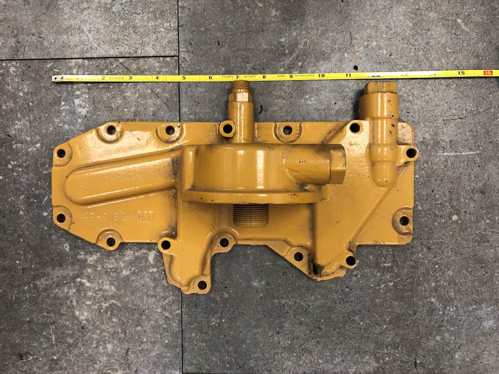
Well yesterday was bipolar. The good news is that everything I've done seems to be working as intended. No leaks. The block heater seals, the oil pan seems sealed. Radiator and intercooler are in. During the test run I found a loose bolt on one of the alternators which I tightened. The wiring is cleaned up and seems to have sufficient strain relief. So, despite my concerns about my projects not working, it seems that everything there is fine. The new oil cooler is in, the lines are run and a hair long but fine overall. No leaks, oil flows through it. The electrical for the oil cooler fan works. We flushed the power steering system and it's back together and topped off. I had to make a bracket for mounting the transmission diptstick now. A lot of little details taken care of.
However during the initial test run, I saw oil dripping on the ground. Upon further inspection, it was coming from the factory oil cooler. It's a steady drip-drip-drip, so not something that I can drive with.
This is annoying for a lot of reasons, not the least of which is that I should've caught this earlier, and I had the coolant drained and basically everything else apart a week ago that is needed to access this area. Plus this is a known weak spot on these engines and something I had a list on to do eventually. But, I didn't do it, so now it's time to do it anyway. I'll feel better once it's done.
Thinking about this I'm pretty certain that this started leaking on the last trip, or maybe the 6Y9 trip (but probably the last trip). After we got back from our last trip that we did, I had noticed that the oil was down. But the oil pan had been leaking ever since I changed the bearings on the engine (that should be fixed now), so I had just assumed that leak had gotten worse. This leak starts as soon as the oil warms up. So I'm sure it was there, draining oil out and clogging up my old radiator and intercooler even further, but it was masked by other items.
So, oh well, next project to do before we can make our next trip.
I wouldn't beat yourself up over that one. Who checks an oil cooler for a leak when you already know you have a pan leak? If you did component tests on every part, the job would probably take 2-3x as long.
Man that sucks. Few things are as frustrating in this world as getting an automotive repair project back together (especially if it involves draining fluids) only to have to tear it right back apart because an item was missed or the repair didn't work. Hopefully you're right and there's a hairline crack or other fatigued spot causing the leak and a new part will solve it.


Somehow I feel like this is all my fault.
Somehow I feel like this is all my fault.
It works! No leaks! Now to get everything else buttoned up…


