Thermocouple Wiring for EGT / CHT

Rob58

Pre-takeoff checklist
Joined
Feb 20, 2016
Messages
360
Display Name

Display name:
Rob
Getting ready to install an engine monitor and trying to get some facts about splicing the thermocouple wires for the EGT & CHT probes. I want to install a firewall connector giving me the ability to easily disconnect the harness when the engine needs to come off occasionally. So I would plan to use gold plated contacts in the connector – does this work without compromising the accuracy of the thermocouple output? What about the overall length of each circuit – do all leads needs to be the same length? Seems like there are some special considerations for thermocouple leads and I would like to learn more about this from some of you experts out there. Thanks!
 
To start, contact the manufacturer of the probes and the display. The installation instructions should have all the details and specifics.
 
My JPI has connectors for all the probes to attach to the wire harnesses. They can all be disconnected to pull an engine, but I am more likely to need to disconnect one to replace a faulty EGT probe these days.
 
Last edited:
What engine? I'm thinking if you are pulling the engine to be shipped off, or even worked on, you will likely pull the sensors at the terminus ie you'd remove the egt probes from each exhaust stack, the cht probes individually.
 
My JPI has connectors for all the probes to attach to the wire harnesses. They can all be disconnected to pull an engine, but I am more likely to need to disconnect one to replace a faulty EGT probe these days.
What type of connector do your JPI probes use? And what kind of wire is used to make the run to the instrument?
 
What engine? I'm thinking if you are pulling the engine to be shipped off, or even worked on, you will likely pull the sensors at the terminus ie you'd remove the egt probes from each exhaust stack, the cht probes individually.
This is an IO-470. Sure your point is a good one and this is one way to do it. However there are times when I might want to pull my engine, maybe to work on the accessory case, and leave all of the manifold wire bundles intact. Regardless I am still trying to understand more about thermocouple leads... how to make connections; what kind of lead wire; the electrical properties.
 
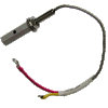
Each of the two wires on every JPI probe has a small bolt and nut that holds the connection to the same type of end fitting on the wiring harness. The picture below is of the OAT probe and end fittings, but all the others are identical.

I don't know what exact kind of wire the harnesses are made of but they are supplied by JPI as part of the package.

IMG_0398.GIF
 
Something on the wires for Alcor type EGT probes:
https://alcorinc.com/PDF/theory_testing.pdf

"Type K, has red (-) and yellow (+) wires and is used on most high temperature EGT/TIT (1200-1700F) applications. It uses chromel and alumel wires in the both the thermocouple element and lead to the meter."
 
I'm not familiar with how JPI or Insight or EI wire their thermocouples, but can tell you standard practices in general. Thermocouple circuits work by measuring the electrical potential differences between two junctions of wires of different compositions (in the case of type K thermocouples, chromel and alumel wires). One junction is the temperature probe and the other junction is a reference (in the past the reference junction typically consisted of the two thermocouple wires connected and kept at a reference temperture (eg., an ice bath)...today the reference junction is emulated electronically). All the wire between the temperature probe and the reference junction should be of the same composition.

Thermocouple circuits are designed to effectively be zero current. In the past this was done with a variable reference voltage source which was adjusted until the reference junction voltage was exactly equal to and opposite of the temperature probe voltage. In modern circuits the circuitry at the reference end is designed to have a very high impedence so that current flow in the wires is essentially zero. Whichever way the circuit achieves zero current, the end result is that differences in the resistance of the wires in thermocouple circuits does not affect the temperature reading. In other words, the length of the wires is not a factor.
 
Back
Top