Static RPM O-200A

cessna1502978

Pre-Flight
Joined
Feb 11, 2019
Messages
35
Display Name

Display name:
Butler2978
Hi all,
I own a 150G and was wondering what the static RPM should be POA says 2500, I can only get 2200. Checked linkage,fuel strainer. Just had annual have good compression. Any thoughts?
 
Have you checked the tach?
How many hours on the cam?
Still have the original prop with no adjustments to the pitch?
 
Prob has been checked cam has not been seance last major good point
 
Tach check is the first thing. As they get old they start to under-read. Next thing is to check the ignition timing. It will have a bigger effect than fuel supply. Poor fuel delivery will make the engine run really badly or not at all. And if the nags havene't been off in more than 500 hours, it's time for an intgernal inspection to make sure the internal timing is still good. A weak spark affects power output, too.
 
Minimum static says 2320, you report 2200. Get ye an optical rpm guage and check it. Those old techs can be 100rpm or so off.
 
Minimum static says 2320, you report 2200. Get ye an optical rpm guage and check it. Those old techs can be 100rpm or so off.
Easily 100 RPM. I have found them nearly 200 RPM low. In Canda we are required to check magnetic-drag-type tachs (which is most of them) annually and they must read within 4% of true at a mid-cruise setting. At 2500 RPM 4% is 100 RPM. The magnets in these things weaken with age and so they don't pull the aluminum cup around far enough. The cup is attached to the needle shaft. That magnet generates an eddy current that creates its own field that interacts with the magnet's field.

At the price of new mechanical tachs, a digital tach makes more sense, and it will stay accurate and does not require an annual check.
 
Easily 100 RPM. I have found them nearly 200 RPM low. In Canda we are required to check magnetic-drag-type tachs (which is most of them) annually and they must read within 4% of true at a mid-cruise setting.
we have no requirement here in the US.
 
we have no requirement here in the US.
I know that. I was just making the point that the tachs get old and start under-reading, and I've found enough of them doing that.

A misreading tach is more of a problem with a CS prop if the mechanic sets the governor to reach redline on an under-reading intrument. It puts the engine over redline.
 
Hi all,
I own a 150G and was wondering what the static RPM should be POA says 2500, I can only get 2200. Checked linkage,fuel strainer. Just had annual have good compression. Any thoughts?

Does it take off good? Does it cruise good? Who cares what the tach says.....
I have owned tons of planes and never even thought about looking at "Static RPM's"
I don't see a point.
 
I know that. I was just making the point that the tachs get old and start under-reading, and I've found enough of them doing that.

A misreading tach is more of a problem with a CS prop if the mechanic sets the governor to reach redline on an under-reading intrument. It puts the engine over redline.
Are we still talking about a Cessna 150-G?
They are equipped with a new type tack (Hysteresis disk). I have not see a magnetic-drag-type since WWII
 
I know that. I was just making the point that the tachs get old and start under-reading, and I've found enough of them doing that.

A misreading tach is more of a problem with a CS prop if the mechanic sets the governor to reach redline on an under-reading intrument. It puts the engine over redline.
It’s my understanding that old tachs over read rather than under. There is a calibrated spring that holds the needle back, and as that spring weakens the tach over reads.
 
As others have stated check the tach accuracy. Do the mags click at the same time when you pull the prop through? How old is your carb? Have you done checked the air box according to the AD? Check that all linkages move to the stops?

I wasn’t getting rated RPM either at first. Swapped carbs and it fixed the problem.
 
Thanks for the replies the plane climbs,cruises great. I will get a tack at some point. Just a fun economical great little bird to play around with. Still waiting on this adsb thing not flying in required airspace up here in the Catskills.
 
It’s my understanding that old tachs over read rather than under. There is a calibrated spring that holds the needle back, and as that spring weakens the tach over reads.
Most often the tach leaks and the oil makes it sticky, then the disks stick
 
It’s my understanding that old tachs over read rather than under. There is a calibrated spring that holds the needle back, and as that spring weakens the tach over reads.
I have found only one tach that over-read, and at least 20 or 25 that under-read.
 
Are we still talking about a Cessna 150-G?
They are equipped with a new type tack (Hysteresis disk). I have not see a magnetic-drag-type since WWII
Same principle. Magnetic eddy-current.
 
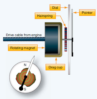
A more common variation of this type of mechanical tachometer uses a magnetic drag cup to move the pointer in the indicator. As the drive shaft turns, it rotates a permanent magnet in a close-tolerance aluminum cup. A shaft attached to the indicating point is attached to the exterior center of the cup. As the magnet is rotated by the engine flex drive cable, its magnetic field cuts through the conductor surrounding it, creating eddy currents in the aluminum cup. This current flow creates its own magnetic field, which interacts with the rotating magnet’s flux field. The result is that the cup tends to rotate, and with it, the indicating pointer. A calibrated restraining spring limits the cup’s rotation to the arc of motion of the pointer across the scale on the instrument face. [Figure 3]


From https://www.aircraftsystemstech.com/2017/05/mechanical-movement-indicators.html

I had one cut open for my students. It was from a 1970s 172. They were all like this.
And while it can be calibrated incorrectly either direction, an aging spring will cause that design to read higher than actual.
 
A more common variation of this type of mechanical tachometer uses a magnetic drag cup to move the pointer in the indicator. As the drive shaft turns, it rotates a permanent magnet in a close-tolerance aluminum cup. A shaft attached to the indicating point is attached to the exterior center of the cup. As the magnet is rotated by the engine flex drive cable, its magnetic field cuts through the conductor surrounding it, creating eddy currents in the aluminum cup. This current flow creates its own magnetic field, which interacts with the rotating magnet’s flux field. The result is that the cup tends to rotate, and with it, the indicating pointer. A calibrated restraining spring limits the cup’s rotation to the arc of motion of the pointer across the scale on the instrument face. [Figure 3]


From https://www.aircraftsystemstech.com/2017/05/mechanical-movement-indicators.html

I had one cut open for my students. It was from a 1970s 172. They were all like this.

To have an eddy current you need 2 disks to produce a pulse, the Hysteresis disk only has 1 disk.

the your example shows this, any oil in the tach will produce friction and change the disk.
 
To have an eddy current you need 2 disks to produce a pulse, the Hysteresis disk only has 1 disk.

the your example shows this, any oil in the tach will produce friction and change the disk.
To demonstrate eddy currents to the class I used to take a powerful supermagnet that had a slot in it (it was from an old hard drive) and a strip of aluminum that fit through that slot loosely. One could slowly push the strip back and forth through the magnet, but if you tried to speed up it resisted the movement. If I held the magnet so the strip fell vertically though it and just let the strip go, it would move slowly through the magnet then fall rapidy to the floor once clear of it. It's the same principle the NDT techs use when they put their eddy-current probe on an aluminum part to look for cracks.

All one needs in the tach is an aluminum cup and a small bar magnet that fits inside it and spins.

The oil-drag thing I found on a tach that went crazy. Needle flying back and forth agaisnt the stops. The needle shaft has the indicator needle on one end and the other end sits in a tiny bushing in the inside end of the tach's input shaft. That keeps things centered. Any oil getting into that bushing there will cause big drag on the needle as it dries out and sludges up and will make the tach over-read. Lots of oil could also, as you say, foul the magnet and cup.

aircraft_10-16.jpg
 
two different concepts, eddy current and hysteresis disk of a tach.
oil will effect the operation of Hysteresis disks because of the fluid coupling principal
Eddy current is a total different concept, an eddy current can operate full of oil, and the fluid coupling will help the operation.
 
Last edited:
Back
Top