[NA]Motorcycle Electrics[NA]

Let'sgoflying!

Touchdown! Greaser!
Joined
Feb 23, 2005
Messages
20,311
Location
west Texas
Display Name

Display name:
Dave Taylor
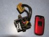
I believe I have a toasted diode in the rectifier of my 1970 CB750. (the battery kept bleeding down; and I read a 0.9v use when the key is off, which disappears when I disconnect the rectifier)

Anyway, does anyone think I can buy replacement diodes and install them?

If not I might (instead of buying a new but rather old fashioned rectifier for 150$) buy a combination electronic VR and rectifier for 225$ which I see available. Although I still like the idea of a 5$ diode which I solder in!
Problem is finding the right one, if they are available at all, and if they can actually be installed in the rectifier as I might hope.

How do I troubleshoot this (see pic) to decide which diode needs replacement?

Either way, I'd like to knock this out asap, riding weather is upon us!
 

Attachments

  • P1010006.JPG
    P1010006.JPG
    206.1 KB · Views: 21
How do I troubleshoot this (see pic) to decide which diode needs replacement?
To troubleshoot a diode, you need to disconnect at least one end of the diode. Then measure its resistance with a VOM meter... el cheapo brands will work fine. Measure using the 100 ohm scale. Place the VOM test leads on each end of the diode, and read the resistance on the VOM. Next, reverse the leads from the VOM - i.e., put the red lead where the black was, and the black lead where the red was - and read the meter again. The reading in ohms should be very high one way, and very low the other way. Very high = many tens of thousands of ohms; very low = 50 ohms or less.

Diodes are like light bulbs in that they either work or they don't. There is no such thing as a diode working at half capacity. Good luck!

-Skip
 
Some say this will work, opinions? Seems crazy cheap.

http://www.radioshack.com/product/index.jsp?productId=2062584

It should work if properly mounted on a heat sink. I would dissipate about 40 W @ 25 amps (same as the original).

Replacing the diodes in the original part would also be OK but that looks like a lot of work to me given the physical makeup. If you go that route, replace all four diodes (if one failed the others were probably overstressed) and pay close attention to the thermal connection between the diodes and the frame. Also note that two of the diodes are in an unusual package with the cathode and anode swapped from the normal arrangement (normal is cathode on the solder terminal, anode on the mounting stud).
 
Individual diodes will either work , or not work. A bridge rectifier curcuit that uses multiple diodes(ussually 4) can work at reduced capacity if only one diode is bad. as noted each diode must be isolated to be tested. a schematic will show which you have and an electronic tech with modest ablilities should be able to build a workable unit from scratch. DaveR
 
Last edited:
Dave's is a 3-phase rectifier

At first I was sure you were wrong but looking closer reveals that you are correct. There are four diodes on the right side in the picture not two and 3 yellow wires (one is well hidden).

and I found plenty of packaged 3-phase bridges for cheap (under $15.00); eg, http://search.digikey.com/scripts/DkSearch/dksus.dll?Detail&name=VS-26MT60-ND

edit: add datasheet reference: http://www.vishay.com/docs/93565/93565.pdf

I see no reason why this would not work famously (would want to mount to some sort of heat sink); I assume his 1970 motorcycle does not have an alternator of greater than 25 amps, but maybe he'll tell us...

You could also use two full wave rectifiers (one ac terminal remains unconnected) which would be a lot cheaper than $15.00 but require soldering a couple more wires.
 
At first I was sure you were wrong but looking closer reveals that you are correct. There are four diodes on the right side in the picture not two and 3 yellow wires (one is well hidden).

Yep, the pic does not make that very clear, but I had the added advantage of having seen a schematic...


DudeWithACoolerAndFasterAirplaneThanMine said:
You could also use two full wave rectifiers (one ac terminal remains unconnected) which would be a lot cheaper than $15.00 but require soldering a couple more wires.

Quite right, but I am worrying about packaging - not sure how much space he has to mount whatever replaces the original - and simplicity.
 
Diodes are like light bulbs in that they either work or they don't. There is no such thing as a diode working at half capacity. Good luck!

-Skip

Not quite true. There is a specified front to back resistance ratio. I have seen diodes with still a high back resistance but not high enough. It resulted in gain being lower than specified for magamp circuit. However, these were electronic circuit diodes and not power rectifiers. I happen to remember it well because I ended up requesting a captains mast over some circumstances surrounding this trouble shooting effort.
 
Last edited:
Back
Top