You are using an out of date browser. It may not display this or other websites correctly.
You should upgrade or use an alternative browser.
You should upgrade or use an alternative browser.
My new Instrument Panel
- Thread starter tonycondon
- Start date

jnmeade
Cleared for Takeoff
What battery size will you use? What is the radio? How much current will this stuff all draw?
tonycondon
Gastons CRO (Chief Dinner Reservation Officer)
Jim,
Ill probably use a 14V battery. The transponder should draw about an amp, the radio is around .5 amps I think. Turn Coordinator is .8 amps and Im not sure about the vario. I probably wont have the Turn Coordinator much.
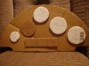
Here is a picture of my first mockup of where I want to place everything. I need to get in the glider and see if I have enough depth for everything. Comment please

Ill probably use a 14V battery. The transponder should draw about an amp, the radio is around .5 amps I think. Turn Coordinator is .8 amps and Im not sure about the vario. I probably wont have the Turn Coordinator much.
Here is a picture of my first mockup of where I want to place everything. I need to get in the glider and see if I have enough depth for everything. Comment please
Attachments
tonycondon
Gastons CRO (Chief Dinner Reservation Officer)
oh its a microair 760 radio
K
KennyFlys
Guest
Where ya gonna mount the low band rig and reel for the long wire? ")
BillTIZ
Final Approach
Why the turn and bank in the Cherokee? planning on some wave flying?
That is a huge transponder box for a small panel. I understand "readily available and cheap" vs. "new, expensive and smaller". They make transponders now about the same size as your radio.
No GPS data logger and an output to the PDA?
That is a huge transponder box for a small panel. I understand "readily available and cheap" vs. "new, expensive and smaller". They make transponders now about the same size as your radio.
No GPS data logger and an output to the PDA?
jnmeade
Cleared for Takeoff
Tony may be thinking of a little incloud work or work at an altitude where the cockpit ices up from the inside.Why the turn and bank in the Cherokee? planning on some wave flying?
jnmeade
Cleared for Takeoff
Tony,
What would happen id you put the AI right in front of you and the radio down to the left of the AI. That might let you put the transponder on an angle on the left side, slanting up.
Oh, I know it would look weird.
What would happen id you put the AI right in front of you and the radio down to the left of the AI. That might let you put the transponder on an angle on the left side, slanting up.
Oh, I know it would look weird.
jnmeade
Cleared for Takeoff
oh its a microair 760 radio
Did you buy this new or used?
TangoWhiskey
Touchdown! Greaser!
Nice, Tony!!
You guessed 0.5A for the radio--is that just with it on and in "listen" mode? How much power does it draw while transmitting? Have you decided on what external antennas to use for the radio and transponder, and where you're going to mount those?
You guessed 0.5A for the radio--is that just with it on and in "listen" mode? How much power does it draw while transmitting? Have you decided on what external antennas to use for the radio and transponder, and where you're going to mount those?
Let'sgoflying!
Touchdown! Greaser!
Is there adequate physical support for the equipment, Tony?
The instruments will mostly be supported by the vertical panel, but that might get a little wobbly with more holes punched in it, the radios will need support in the rear...well at least the txpr will.
Is there enough room, fore and aft?
also as you move fwd from the panel, the fuse might narrow
Looks pretty cool.
foka4
Pre-takeoff checklist
- Joined
- Oct 31, 2006
- Messages
- 236
- Location
- Ankeny (Des Moines), IA
- Display Name
Display name:
Matt Scudwalker
When I was in high school, I always thought it would be cool to mount some gauges on the hood of my Camaro. I think the nose of the Cherokee would be equally suitable. Plus, the plumbing would be really simple.
tonycondon
Gastons CRO (Chief Dinner Reservation Officer)
Why the turn and bank in the Cherokee? planning on some wave flying?
That is a huge transponder box for a small panel. I understand "readily available and cheap" vs. "new, expensive and smaller". They make transponders now about the same size as your radio.
No GPS data logger and an output to the PDA?
Im not planning on wave flying. I am thinking of putting the turn coordinator in for a few reasons. One reason is because I have it. Second is because the Cherokee has wimpy airbrakes and I want to have it if I need it. In Iowa there were a few times where I was having to push the nose down and pull the brakes to stay out of the clouds. The lift is generally not weaker in Kansas. I will probably not normally run the Turn Coordinator until I get close to cloudbase.
You understand the transponder size issue just fine. I got this one for about 1/3 of the price of a new microair or becker. It will draw a lot of power, about an amp, but for me to feel comfortable operating out of the Wichita Gliderport, I need it. Otherwise it will be a 45 minute drive to hutchinson, which will eliminate after work fun flights.
I think it looks like a great layout.
Is there anything else you might, someday, want, that you should make allowance for?
i don't think so really. i might change out the vario or something but I think it has all the basics I will need.
Tony,
What would happen id you put the AI right in front of you and the radio down to the left of the AI. That might let you put the transponder on an angle on the left side, slanting up.
Oh, I know it would look weird.
That would look weird. I dont think it will make much of a difference though. The transponder is sorta deep and needs to be towards the center. I really gotta take all the stuff out to the glider and make sure I'll have enough depth.
Did you buy this new or used?
The radio was a graduation gift from the fine people of PoA. Thanks again everybody!
Nice, Tony!!
You guessed 0.5A for the radio--is that just with it on and in "listen" mode? How much power does it draw while transmitting? Have you decided on what external antennas to use for the radio and transponder, and where you're going to mount those?
I guessed wrong. It draws .1 amps when receiving and 1.8 amps when transmitting. I would not be spending very much time transmitting, so average would probably be well below .5 amps. I will mount the antennas internally. I think I'll use a dipole that is basically a stick on for the transponder. Im not sure what antenna I will use for the comm. Either way both will be mounted inside the tail of the glider. Thats one nice thing about a wood frame and fabric covering
tonycondon
Gastons CRO (Chief Dinner Reservation Officer)
Is there adequate physical support for the equipment, Tony?
The instruments will mostly be supported by the vertical panel, but that might get a little wobbly with more holes punched in it, the radios will need support in the rear...well at least the txpr will.
Is there enough room, fore and aft?
also as you move fwd from the panel, the fuse might narrow
Looks pretty cool.
dave, there is a sort of floor that runs back into the nose from the bottom of the panel, which would be very convenient support for the transponder. I plan to use .1" thick aluminum for the panel, which I think will be stiff enough to support the rest of the stuff. The fuse definitely narrows towards the nose, which is why the Transponder and Turn Coordinator are more or less centered. Like I said, I really need to take everything out to the glider and make sure there is enough room.
When I was in high school, I always thought it would be cool to mount some gauges on the hood of my Camaro. I think the nose of the Cherokee would be equally suitable. Plus, the plumbing would be really simple.
that is a fascinating idea, could fair it in. Would be like a HUD display.
Rob Schaffer
Cleared for Takeoff
I'm surprised that no-one commented yet on his creativity of instruments on his mockup panel I'm likin the detail on the altimeter. At least you are on the ground with the transponder off, but I think your Kalsman window needs some adjustment,... either that, or it's a really really low pressure system that's moved through.
I'm likin the detail on the altimeter. At least you are on the ground with the transponder off, but I think your Kalsman window needs some adjustment,... either that, or it's a really really low pressure system that's moved through. tonycondon
Gastons CRO (Chief Dinner Reservation Officer)
What No Comapss?????
i think i'll start that paperwork next week.
gismo
Touchdown! Greaser!
Jim,
Ill probably use a 14V battery. The transponder should draw about an amp, the radio is around .5 amps I think. Turn Coordinator is .8 amps and Im not sure about the vario. I probably wont have the Turn Coordinator much
If everything will run on 14-28 volts, I recommend you use two 12v batteries in series. While 14v (seven 2v cells) is much better than 12v, you won't be able to use off the shelf chargers and desulphators with that arrangement. If you have something that won't run on the higher voltage you should consider trading for one that will or adding a small switching (high efficiency) down converter.
You might want to consider grouping the instruments into an IFR group and a VFR group with separate switches. I'd also add a dedicated LCD volt/ammeter (might double as a clock) or at least a voltmeter preferrably one with a programmable low voltage alarm. Your battery life will be greatly improved if you avoid deep discharge and it's always nice to have an indication of how much charge is left in your battery especially when you're in IMC. Fortunately, lead acid batteries exhibit a predictable relationship between charge level and voltage with a constant load.
I'd also include at least two outlets mounted in a way that can be reached in flight (but doesn't put the plugs/cords in the way) for external accessories like a PDA or handheld GPS.
gismo
Touchdown! Greaser!
I think I'll use a dipole that is basically a stick on for the transponder. Im not sure what antenna I will use for the comm. Either way both will be mounted inside the tail of the glider. Thats one nice thing about a wood frame and fabric covering
A dipole by definition has two poles. Most aircraft antennas are monopoles and require a ground plane to work properly. There are some antennas designed to go inside plastic airplanes and I'm pretty sure I've seen plans for homemade versions that you could easily make for next to nothing.
brcase
En-Route
Tony,
What kind of GPS/PDA are you using?
For reference my HP pulls about .4 amps IIRC with everything running and not transmitting. Of course I am not running a transponder.
I my opinion I think you are going to need to 14 volt batteries at least for the transponder. My recommendation is to run the transponder on its own battery.
Your Panel lay out should work fine but I would do it differently. I would put the ASI on the left side, the Vario on the top. Altimeter on the Right and the TC on the lower right. That is just my opinion.
Of course if you decide to do any contest flying you will need to remove or disable the TC.
Brian
tonycondon
Gastons CRO (Chief Dinner Reservation Officer)
If everything will run on 14-28 volts, I recommend you use two 12v batteries in series. While 14v (seven 2v cells) is much better than 12v, you won't be able to use off the shelf chargers and desulphators with that arrangement. If you have something that won't run on the higher voltage you should consider trading for one that will or adding a small switching (high efficiency) down converter.
You might want to consider grouping the instruments into an IFR group and a VFR group with separate switches. I'd also add a dedicated LCD volt/ammeter (might double as a clock) or at least a voltmeter preferrably one with a programmable low voltage alarm. Your battery life will be greatly improved if you avoid deep discharge and it's always nice to have an indication of how much charge is left in your battery especially when you're in IMC. Fortunately, lead acid batteries exhibit a predictable relationship between charge level and voltage with a constant load.
I'd also include at least two outlets mounted in a way that can be reached in flight (but doesn't put the plugs/cords in the way) for external accessories like a PDA or handheld GPS.
The guys i've seen who use 14 V setups us a 6V and two 4V batteries, or a 12V and a 2V. The Microair radio cannot handle over 16V. the turn coordinator is also labeled as 14V. Wingsandwheels.com sells 14V battery chargers.
The plan is the Turn Coordinator, Radio, and Transponder would all have their own circuit breaker switches. I'd like to get some sort of volt meter too...will have to look around and see what is available.
Im pretty sure that PDAs and GPSs in gliders are usually sort of hard wired in, instead of ran off a cigarette lighter.
tonycondon
Gastons CRO (Chief Dinner Reservation Officer)
Tony,
What kind of GPS/PDA are you using?
For reference my HP pulls about .4 amps IIRC with everything running and not transmitting. Of course I am not running a transponder.
I my opinion I think you are going to need to 14 volt batteries at least for the transponder. My recommendation is to run the transponder on its own battery.
Your Panel lay out should work fine but I would do it differently. I would put the ASI on the left side, the Vario on the top. Altimeter on the Right and the TC on the lower right. That is just my opinion.
Of course if you decide to do any contest flying you will need to remove or disable the TC.
Brian
I don't fly with a GPS or PDA. I do have an old palm pilot with soar pilot on it, but i've never come up with a good way to mount it in the cockpit. its cramped enough in there.
Putting the TC on the side could prove problematic since the thing is like a foot deep. Im pretty sure it would rub on the sides of the nose if it was too close to the edge.
brcase
En-Route
<snip> I will mount the antennas internally. I think I'll use a dipole that is basically a stick on for the transponder. Im not sure what antenna I will use for the comm. Either way both will be mounted inside the tail of the glider. Thats one nice thing about a wood frame and fabric covering
As far as the Comm Antenna goes, I have a friend with a Pik20 that needs a new antenna. I checked with my Radio guy and he recommended taking a peice of Coax (not sure what kind, I don't know if he is going to use RG58 or something better) and stripping the outer insulation off of about 18 inches (I don't recall what the 1/4 wave length is, that is why I am having my radio guy do it) of the coax. Then carefully work the outer braid so that it folds over the outer insulation back down the coax. I hope that makes sense. So now you have the about 18 inches of the outer braid on the outside of the insulation going back toward the radio and about 18" of the inner wire and with the inner insulation protruding from the end of the coax. We are just going to glue this vertically to the back of the vertical Spar in the vertical fin. This makes for a very inexpensive dipole antenna.
If you need a better description let me know and I can find out what the 1/4 wave length should be and what kind of cable to use.
Brian
tonycondon
Gastons CRO (Chief Dinner Reservation Officer)
brian,
interesting, tell me more. although, im not sure that i have 36" or more of vertical space available anywhere. worth checking into though.
interesting, tell me more. although, im not sure that i have 36" or more of vertical space available anywhere. worth checking into though.
CJones
Final Approach
Check a local pick-n-pull junkyard for a voltmeter. Not sure how efficient they are, but most automotive Voltmeters are 4-18V IIRC. Or how about a simple handheld multimeter that is hard-wired into the system that you can simply flip on-and-off when you want. Then you can get different information if you want - V, A, etc.
Actually, I have no clue what would work - I always try to think of the most jerry-rigged way to do it anyway.
Actually, I have no clue what would work - I always try to think of the most jerry-rigged way to do it anyway.
vontresc
En-Route
Actually the voltmeter idea is a good one. A guy in Marfa showed up with a Ximango Motorglider. He had one of the teeny Radio Shack multimeters velcroed to the panel. Pretty cool setup.
ScottM
Taxi to Parking
- Joined
- Jul 19, 2005
- Messages
- 42,529
- Location
- Variable, but somewhere on earth
- Display Name
Display name:
iBazinga!
When Tony said he wanted to do a dipole this is EXACTLY what I was thinking of in its construction. I have been making dipoles this way since I was in HS.As far as the Comm Antenna goes, I have a friend with a Pik20 that needs a new antenna. I checked with my Radio guy and he recommended taking a peice of Coax (not sure what kind, I don't know if he is going to use RG58 or something better) and stripping the outer insulation off of about 18 inches (I don't recall what the 1/4 wave length is, that is why I am having my radio guy do it) of the coax. Then carefully work the outer braid so that it folds over the outer insulation back down the coax. I hope that makes sense. So now you have the about 18 inches of the outer braid on the outside of the insulation going back toward the radio and about 18" of the inner wire and with the inner insulation protruding from the end of the coax. We are just going to glue this vertically to the back of the vertical Spar in the vertical fin. This makes for a very inexpensive dipole antenna.
If you need a better description let me know and I can find out what the 1/4 wave length should be and what kind of cable to use.
Brian
For the length of the dipole the equation is L(ft)=468/F in MHz
brcase
En-Route
I don't fly with a GPS or PDA. I do have an old palm pilot with soar pilot on it, but i've never come up with a good way to mount it in the cockpit. its cramped enough in there.
Putting the TC on the side could prove problematic since the thing is like a foot deep. Im pretty sure it would rub on the sides of the nose if it was too close to the edge.
I was afraid that was what you were going to say about the GPS/PDA. I would be looking at mounting this instead of the TC, it would have a lot more functionality than the TC. However You could put a mount over the front of the TC. That way you could just remove the PDA from the mount when you wanted to use the TC.
You have seen my panel I run an old compaq 1550 or 1520 PDA mostly because it is cheap and is easy to see in the sunlight. I also have the old Free Cambridge Software (Newer version is Glide Navigator II) for these PDA's. Of course these require a separate GPS but an old serial GPS can easily be had for less than $100, The 15xx PDA's are a bit hard to find now but can usually be had for between $10 and $50. They will usually need a new battery for $15. I am now running XCSoar on my 1550 which is free. So you could get a system like mine for probably less than $150.
However I don't know to much about them but the XCSoar Developers have been porting it for many of the Personal Navigator Assistants (PNA) The HP31X series seems to be a popular one and some of the MIO series, I don't know what other ones it is currently running on. But these can be had for less than $200 and are self contained and would easily fit in the space that your TC uses, or over the top of it.
I didn't run the PDA in my 1-26 but I did use my Garmin12xl GPS in it. Knowing this distance to the airport makes it a lot easier to calculate the alititude required, Of the course the PDA will do the calculation for you.
Brian
Attachments
tonycondon
Gastons CRO (Chief Dinner Reservation Officer)
good points brian. i will reconsider this. if i'm leaning towards changing anything it would be to pull that turn coordinator. the more i think about it, the heavier it is, and a power hog. Ive got another vario I could put in that hole, or I could use the space for the PDA.
btw its a really old black and white Palm Pilot. it has a GPS antenna that goes into the serial port. I'll have to pull it out of the box and power it up, see how it will fit in the panel
btw its a really old black and white Palm Pilot. it has a GPS antenna that goes into the serial port. I'll have to pull it out of the box and power it up, see how it will fit in the panel
vontresc
En-Route
Tony, my friend Dave in our club brought his HP PNA to your last club meeting with See You mobile installed on it. That was a slick setup. Although you won't be able to use the log files for badges and records, this setup was perfectly OLC legal, and best of all it was self contained. PDA and GPS in one unit with a pretty good daylight readable display. I don't know how long the internal batteries in that unit last, but I bet you could figure out how to mount a flexible boom in there someplace.
Darn this reminds me I need to write up a simple OLC guide for out club.
Darn this reminds me I need to write up a simple OLC guide for out club.
gismo
Touchdown! Greaser!
brian,
interesting, tell me more. although, im not sure that i have 36" or more of vertical space available anywhere. worth checking into though.
You can get away with "bending" the dipole about 30 degrees to make it fit. The 1/2 wavelength for 108-136 MHz is 110-140 cm or 43-57 inches. Antenna elements are typically shorter by 5-10% to accommodate the lower propagation velocity in conductors vs a vacuum. You either need a 1/4 wave radiator mounted on a 1/2 wave diameter ground plane or a 1/2 wave dipole unless you use "loaded" elements to reduce the dipole's length. Wavelength in meters = 300/frequency.
Bob Archer (Sportcraft Antennas) has designs that might fit. I think Aircraft Spruce sells them. You could work up your own design at a lower cost but considerably more effort.
Last edited:
gismo
Touchdown! Greaser!
Check a local pick-n-pull junkyard for a voltmeter. Not sure how efficient they are, but most automotive Voltmeters are 4-18V IIRC. Or how about a simple handheld multimeter that is hard-wired into the system that you can simply flip on-and-off when you want. Then you can get different information if you want - V, A, etc.
Actually, I have no clue what would work - I always try to think of the most jerry-rigged way to do it anyway.
Most automotive aftermarket voltmeters are mechanical meters that draw considerable current for themselves and wouldn't be a good idea for a glider. There might be some LCD models that would be fine. I don't think that wiring in a handheld multimeter would be a good idea. To get both voltage and current readings would require a complicated switching arrangement.
Capt. Geoffrey Thorpe
Touchdown! Greaser!
- Joined
- Jun 7, 2008
- Messages
- 15,645
- Location
- DXO124009
- Display Name
Display name:
Light and Sporty Guy
I don't fly with a GPS or PDA. I do have an old palm pilot with soar pilot on it, but i've never come up with a good way to mount it in the cockpit. its cramped enough in there.
I asume there is no room to put the transponder at an angle right in front of the seat (under your knees)?
Of course, you would want a spash shield for when you make long flights and, uh... well, you know... uhhh - never mind.
tonycondon
Gastons CRO (Chief Dinner Reservation Officer)
I asume there is no room to put the transponder at an angle right in front of the seat (under your knees)?
Of course, you would want a spash shield for when you make long flights and, uh... well, you know... uhhh - never mind.
there might be options for transponder mounting that doesnt involve the instrument panel, i'll have to investigate that when I've got everything out at the glider.
tonycondon
Gastons CRO (Chief Dinner Reservation Officer)
Most automotive aftermarket voltmeters are mechanical meters that draw considerable current for themselves and wouldn't be a good idea for a glider. There might be some LCD models that would be fine. I don't think that wiring in a handheld multimeter would be a good idea. To get both voltage and current readings would require a complicated switching arrangement.
i swear at one point i found a simple voltmeter that was just a 3 or 4 digit LCD readout, with a couple wires coming off of it. Now all I can find are kits for similar setups, but nothing assembled for sale. That would be ideal, IMO
brcase
En-Route
brian,
interesting, tell me more. although, im not sure that i have 36" or more of vertical space available anywhere. worth checking into though.
Tony, here what my friend said about the coax comm antenna.
As far as dimensions, the shield folded back over the coax should be 22 inches and the protruding wire should be 23 inches. This is a starting point. The two pieces (shield and wire) can then be shortened as bit at a time until the SWR is in the area of 1.25 to 1. Any good quality 52 ohm coax will work.
vontresc
En-Route
i swear at one point i found a simple voltmeter that was just a 3 or 4 digit LCD readout, with a couple wires coming off of it. Now all I can find are kits for similar setups, but nothing assembled for sale. That would be ideal, IMO
Check Digikey.com
http://search.digikey.com/scripts/DkSearch/dksus.dll?Detail&name=227-1042-ND
there are plenty more as well
brcase
En-Route
i swear at one point i found a simple voltmeter that was just a 3 or 4 digit LCD readout, with a couple wires coming off of it. Now all I can find are kits for similar setups, but nothing assembled for sale. That would be ideal, IMO
Here is an old post from rec.aviation.soaring. I just checked and it is still available but a bit pricey. current price is about $33.
For those wanting a very small, accurate and inexpensive LCD voltmeter, I
found one.
Size is 43.5mm (1.71") wide, 21.4 (.84)
tall, 5.5 (.22) thick. Two wires (red, black) exit a 5.5mm (7/32") threaded
stud on rear of unit which is also used for panel mounting. Color is silver
gray. LCD is 3 digits (00.0) size is 12.5 mm (.5").
I purchased two units (to avoid Allied's minimum order SC) and both are
accurate as checked by my Fluke meter. There is a calibration pot on rear of
module should that be required. Input measuring range is from 4 to 25 VDC.
Current consumed by unit is 3 ma. max . . . I measure current draw at 9 VDC
at 1 ma.
http://www.alliedelec.com/
Allied part # 572-0002
Mfg. # EMV1200
Price $24.95 (USD)
Mfg. is Lascar Electronics Ltd. (UK)
www.lascarelectronics.com
Pictures are on this site, look under EM series.
- Joined
- May 18, 2007
- Messages
- 6,730
- Display Name
Display name:
jsstevens
[snip]
Of course if you decide to do any contest flying you will need to remove or disable the TC.
Not being a glider pilot myself, why is the TC not legal for contest flying?
John