Garmin GDL 82 advice needed

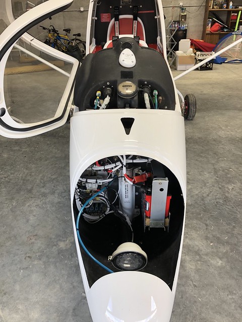
I have to take a moment to brag on my plane a little.

I can have my panel disconnected and on my bench in about 10 minutes:

49278935122_2fa64e3638_z.jpg


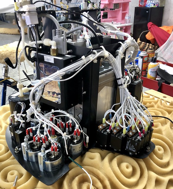
That makes things SO much easier to work on than any plane I’ve ever worked on.

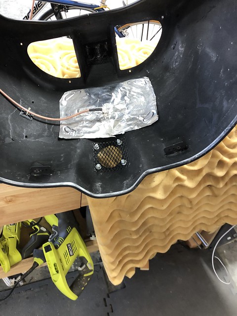
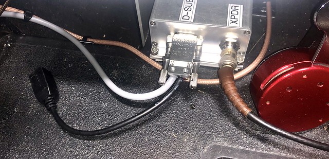
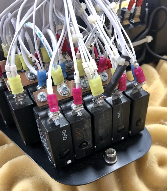
For instance, tapping into my transponder breaker was trivially easy - it’s the middle one on the bottom row:

49278935087_e95b02005e_z.jpg


I had considered some sort of black covering to control the glare. I was thinking black tape, but felt is not a bad idea either.

Now to just throw things back together and hope for the best!
 
I thought my instrument panel was easy to work on, once you take off the cover (5 screws):

DSCN5874.jpg

...but yours is incredibly maintenance-friendly. By the way, you can see the GDL 82 power wire attached to the Transponder CB (top left). All of the wires in my airplane are laser labelled. If the printing weren't so darned small, you could easily find the wire you were looking for among bundle of 2 dozen...
 
Thanks for all the input.

I had the foresight to order my GPS cable with a right angle TNC connector for the antenna. But reassembling the panel, there was still interference with the case of the Dynon D10A which was longer than I remembered. So I had to move the mount forward, and figured I’d use the opportunity to put it in its correct orientation:

49279828941_585f94933d_z.jpg


If you look closely, it’s a little crooked - there was still some interference with the Dynon. Next time I have the panel out I’m going to insert some spacers at the front to both buy me a little more clearance and to get the antenna closer to level.

I also stole one of Karen’s brownie pans for a ground plane:

49279353168_a9698df896_z.jpg


I have no separate ground for the antenna. If there’s a problem, easy to go back and add one. Power and ground to the unit taken care of, piggy-backing the power off the existing 5A transponder breaker.

Only 1” canopy clearance. Right now, it’s pretty much a matter of programming testing it and testing it and then fine-tuning if need be.

To be continued...
 
Last edited:
Nice job ! The ground plane below the gps antenna is not necessary, but WILL help shield the gps antenna from interference.
 
Programming done.

I’m pretty worthless with Windows, and it took the tech-savvy brother of my friend to get the Garmin install program running properly and recognizing my unit. But once it did, the process was straightforward.

49289556217_0146f0886a.jpg


Showed 2 faults, but they seemed to resolve themselves:

49288860403_3900a7a920.jpg


If rain holds off may do the test flight tomorrow around Knoxville.
 
Got up a little while ago before the rain moved in and did a big circle around KTYS in Knoxville.

49294633207_cffdb46244_z.jpg


Approach confirmed they were receiving my ADSB Out, and on landing I submitted my flight to the FAA for a Performance Review. Within 10 minutes I got an email with the report and nothing highlighted in red. Woo Hoo!

I usually expect things like this not to work at first and require troubleshooting - it seemed like a lot of little “it should work” fudges but glad it worked first time out.

Thanks for the help and support!
 
Following this thread with great interest. I just bought the GDL 82 but won't see it for a month or so as I am at sea. I am a bit frustrated with trying to envision how the USB plugs into the thing. I am guessing you pull the RS232 out of the box and the connector is stuffed in there somewhere? Also, did anyone wire a failure annunciator light and/or anonymous mode switch? I would love to see some examples of those!
 
When you wire the multipin connector, 4 of the pins go to the 4 wires of the USB4 female connector. Mine just tucks in out of the way, though I suppose it could be mounted somehow.

49416735601_8c65c3e711_z.jpg


Someone else will have to comment on the “extras”, though they’re covered in the installation manual, available online. I kept mine bare-bones.
 
Ok....so you have to strip a USB wire and pin it to the multipin connector????
They seemed to gloss over that in the installation manual. It reads as though the USB B connector is already in/on the box somewhere!
 
The USB 4 connector is included, with 4 color-coded wires. See wiring diagrams and unboxing photo upthread.

The unit can be ordered with a custom harness. In that case it may come pre-wired, at a cost. In addition to those 4 wires, only power and ground are required for the base installation.

It does not come with the USB2 to USB4 cable. I happened to have one in a box of old computer cables - from an old hard drive, I think.
 
Ahhhh, that makes sense thank you. It was difficult to make that out with what I have here.
It looks like the anonymous mode switch is fairly simple to install too, something I will definitely be doing. It appears to be a switch that grounds pin 5. The other discrete switch is the failure annunciator which also seems to be straightforward and worthwhile too.
 
Back
Top