Citation Temp Probe anti/de-ice Heater?

jspittler

Filing Flight Plan
Joined
Sep 4, 2006
Messages
26
Location
Upland, CA
Display Name

Display name:
Judd Spittler
Since I don't fly/maintain/design Cessna Citations or their engines, we can file this question as merely a technical curiousity on my part...

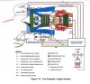
Part of the design of the P&W JT15D engine (and maybe some or all others) is a temp sensor that measures the incoming air temp. I understand that this sensor is protected from icing using bleed air from the compressor...

Ummmm, what?

I guess my question is this... how does this work? If you are trying to measure free air temp, how do you do it with a heated temp probe? :) Anyone have any insight into this?

Inquiring minds want to know!

Judd
 
Re: the heated air temp probe. It works by measuring the current increase required to maintain the heated probe at a specific setting as the on rushing free air tries to cool it down.
As the probe is cooled it requires more current to maintain it's heated condition: the amount or increased current is corelated to a specific temperature. The probe is similiar to the method of calculating air mass flow in many modern fuel injected cars ( air mass meters/hot wire)

The particular device I am asking about is heated using bleed air, rather than an electrical source. I don't know if it is doing a similar thing, or not.

Judd
 
It's a jet. You just sacrifice a chicken before each flight and you're good to go.

And you sacrifice said chicken by freezing it, running the jet up to full power, and tossing it through the engine. :rofl:

At least that's how the FAA certification folks do it...
 
Re: the heated air temp probe. It works by measuring the current increase required to maintain the heated probe at a specific setting as the on rushing free air tries to cool it down.
As the probe is cooled it requires more current to maintain it's heated condition: the amount or increased current is corelated to a specific temperature. The probe is similiar to the method of calculating air mass flow in many modern fuel injected cars ( air mass meters/hot wire)

I don't know much about hot wire probes, but they're actually measuring the rate of heat loss from the probe by measuring the amount of electrical current required to maintain the wire at temperature, as you described. The heat transfer from the probe will be a function of the geometry (which is known), the air density (which obviously varies a lot), the air velocity, and the air temperature (which is what you're trying to find out).

If this is on an engine, it might not be very easy to figure out the air velocity without using information on thrust setting and aircraft velocity. You could also use the pressure altitude information, and then the only unknown would be temperature. So is the probe you describe simply inputing the required electrical current to a flight computer system which then uses all the other factors to figure out air temperature, or is it somehow trying to come up with the temperature on its own without taking into account the velocity and pressure of the air?

Chris

As I said earlier, the system does not seem to operate as acrodisiac suggested, but I can at least pass on some of my limited understanding on the system. My information comes from the maintenance manual for the engine (ain't Ebay great?).

The idea is that you want to have a cockpit indication of interturbine temperature (ITT). My understanding is that this is kind of hard to measure directly. Someone figured out that if you measure temps at a couple of other points in the system, you can do some math and recreate a usable estimate of ITT.

The "math" in this case, is actually done in "analog" form simply by the way the thermocouples are connected to each other. In case you are curious, the ITT is estimated to be the exhaust temp + 3x the temp rise in the bypass duct. Supposedly the ITT reading in the cockpit is read directly from the output of this circuit of thermocouples. I do not believe that any altitude or airspeed corrections are made.

As far as my original question, I am still not sure about the bleed air heating the temp probe thing, but someone suggested that the bleed air doesn't directly heat the temp probe, but is part of a novel design that somehow allows the unheated air to reach the temp probe, while at the same time prevents the probe from icing up. It sounds like an interesting design, so that is why I am kind of curious about it.

Judd
 
The idea is that you want to have a cockpit indication of interturbine temperature (ITT).
I can't help you with the design of that heated temperature probe but I think you may have two different probes confused. The first temperature probe you mentioned (the heated one) is located outside the engine in the opening of the nacelle. Since it's outside it is prone to icing up, hence the need for heat. The ITT probe is inside the engine between the turbine sections. It doesn't need to be heated because the temperature in there is in the multiple hundreds of degrees C. Maybe this diagram will make it clearer. This is a TFE731 engine which is different than the one on the Citation but I can't imagine it's too much different. As far as the heated probe goes, though, this one is heated electrically.
 

Attachments

  • TFE731.JPG
    TFE731.JPG
    64.3 KB · Views: 23
...
The "math" in this case, is actually done in "analog" form simply by the way the thermocouples are connected to each other. In case you are curious, the ITT is estimated to be the exhaust temp + 3x the temp rise in the bypass duct. Supposedly the ITT reading in the cockpit is read directly from the output of this circuit of thermocouples. I do not believe that any altitude or airspeed corrections are made.

Mari's right, you're clearly describing too different systems. A thermocouple measures temperature directly with no correction required for density or anything. However, you originally described a hotwire which works on very different principles. The original poster is asking about the inlet probe. Can you verify the type of sensor used for the inlet probe using your maintenance manual? If it really is protected by a bleed air system, I'd love to understand how. The original poster's question is an excellent one.

Chris
 
Those heated probes just work like a constant temperature hot-wire anemometer. The heating only changes the reference baseline voltage when measuring the resistance changes due to temperature.
 
I can't help you with the design of that heated temperature probe but I think you may have two different probes confused. The first temperature probe you mentioned (the heated one) is located outside the engine in the opening of the nacelle. Since it's outside it is prone to icing up, hence the need for heat. The ITT probe is inside the engine between the turbine sections. It doesn't need to be heated because the temperature in there is in the multiple hundreds of degrees C. Maybe this diagram will make it clearer. This is a TFE731 engine which is different than the one on the Citation but I can't imagine it's too much different. As far as the heated probe goes, though, this one is heated electrically.

The JT15D engine does seem to be a bit different. There really doesn't appear to be an actual ITT sensor in this one, this temp is derived from other temp measurements. The fuel control unit has it's own temp sensor which is not the one I am talking about.

I was looking for a concise description of how this one works, but looks like I will have to cut and paste to keep it readable. The following is taken from the JT15D-1/4 Maintenance Manual (the bold print is really the key to the implementation):

P&W JT15D-1/4 Maintenance Manual said:
ITT SENSING SYSTEM DESCRIPTION AND OPERATION

1. General

The interturbine temperature (T5) sensing system provides the pilot with an indication of the engine operating temperature. The temperature sensing system consists of integrated T1 and T6 systems from which a simulated interturbine temperature (T5) readout is computed...

...

3. Operation

A simulated interturbine temperature (T5) readout is computed by adding three times the air temperature rise across the bypass duct to the exhaust temperature and standardizing this temperature range through a variable resistor. By sensing the inlet and outlet temperatures of the bypass air stream, rise in air temperature through the bypass duct can be established by subtracting inlet from outlet temperature. This is accomplished via the TI probes and as each probe contains three thermocouples connected in series, rise in temperature is multiplied by three to provide the required readout. The T6 thermocouple probes are connected in parallel through the wiring harness to provide an average exhaust temperature and, with the T6 and T1 harnesses connected in series, a total readout of T6 plus three times the rise in bypass air temperature is provided as the output signal.

Basically the T1 system measures the temp difference across the bypass fan... and does it using three pairs of temp sensing thermocouples wired in series to result in 3x the otherwise measured temp diff. Each Pair of thermocouples straddles the bypass fan. The T6 system measures the exhaust temp. These two circuits connected in series which results in the outputs being added together. This accomplishes the required math for synthesizing the desired ITT temp value (the math is not done in a computer). The output of this circuit is a pair of wires that goes to the ITT gauge in the cockpit.

Judd
 
Can you verify the type of sensor used for the inlet probe using your maintenance manual? If it really is protected by a bleed air system, I'd love to understand how. The original poster's question is an excellent one.

Chris

If it helps at all, I have attached a schematic of how the thermocouples are wired up. The T6 thermocouples are located in the exhaust stream, past the last turbine.

It seems to be a clever circuit. It is interesting that the mathematical relationship between the exhaust temp, the bypass temp rise and the ITT exists.

Judd
 

Attachments

  • Thermocouples.png
    Thermocouples.png
    22 KB · Views: 8
If it helps at all, I have attached a schematic of how the thermocouples are wired up. The T6 thermocouples are located in the exhaust stream, past the last turbine.

It seems to be a clever circuit. It is interesting that the mathematical relationship between the exhaust temp, the bypass temp rise and the ITT exists.

Judd

You're right, it is a clever little system they have there.

The original poster is asking about the engine inlet temperature, I believe (that's the only one that would need de-icing, as far as I can tell). Does this engine have such a thing? It would be right at the front before the first compressor blades.

Chris
 
Those heated probes just work like a constant temperature hot-wire anemometer. The heating only changes the reference baseline voltage when measuring the resistance changes due to temperature.

Ok, given that these probes are also used to measure wind speed, you must be forced to use some sort of correction for known velocity and pressure altitude in order to extract the air temperature, correct?

Chris
 
According to the Goodrich sensor website

"Unique design characteristics ensure that engine or probe deicing heat does not affect sensor performance."

Basically the probe is shrouded such that the air is not moving in relation to the probe.

http://en.wikipedia.org/wiki/Total_air_temperature

I came across this regarding air temperature measurement at high altitude, too...

"it is also difficult to measure the total air temperature accurately"

http://mtp.jpl.nasa.gov/notes/sat/sat.html

which has some example calculations.

We used an adaptation of hot-wire anemometer technology to operate sump pumps under the reactor vessel at the power plant I use to work at. The water temperature could be as high as 212 F but since the probe operated around 325 F it could respond to the difference in radiative cooling in air versus conduction/convection in liquid water. By adjusting the reference voltage we could change the water level at which the probe would trigger the pump motors. The probe was much more rugged than the standerd capacitance style immersion probes. We put shrouds around them, too, to eliminate false indications when the water swirled in the sump.


Ok, given that these probes are also used to measure wind speed, you must be forced to use some sort of correction for known velocity and pressure altitude in order to extract the air temperature, correct?

Chris
 
According to the Goodrich sensor website

"Unique design characteristics ensure that engine or probe deicing heat does not affect sensor performance."

Basically the probe is shrouded such that the air is not moving in relation to the probe.

http://en.wikipedia.org/wiki/Total_air_temperature

Aha! So the probe is interested in the total temperature! I thought we were measuring outside air temperature (static temperature). In retrospect, it makes sense that total temperature would be more important in a jet engine, I suppose. Well, that removes the problem of accounting for the velocity (since total air temperature is measured after bringing the air to a rest), but I think that the altitude would still have a significant effect if you're using a hot-wire. You get much greater cooling with high densities, so higher altitudes would give higher temperature readings. So, as long as you're measuring pressure as well and using a computer to compensate, you'd be good to go.

Chris
 
Back
Top