ELT's Which one. ?

Instead of getting ****y why don't you just fill in the blanks and add a photo or two of your shelf?

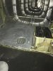
My Cessna's ELT was moved from the baggage area skin to the stringers under the baggage floor. It passes the 100# test easily. My Cub's ELT is attached to tubes above the aft baggage. The DAR gave it some pretty good tugs as part of my inspection. It was one of his priorities.
There is no doubt the ELT must be mounted correctly, and this one will be, Cessna built the C-182 Equipment shelf for this purpose. It is strong enough to support the Battery, and several other pieces of radio equipment, and pass certification requirements, it should support the ELT OK, but we will see what the ELT instructions say. (it should be here this week)
.070" 2024-T3. ?? YGTBSM This is a mount for a ELT, not a patch on a Russian battle ship.

The battery in my Dad's 182 is not on that shelf, it is next to it, and has a whole lot more substance to it than that shelf. You would have to mount the ELT directly to the longitudinal hat under it, but really, you'll only be able to attach one side of the ELT to it.
 
I've done that, but .040" is thick enough if you bend flanges on the uprights as well. The bottom is wide enough plus a bit for the ELT tray, the verticals about an inch or a bit less, and the flanges at the top about a half inch. They keep the verticals from buckling under downward load. The early part of AC43.13-2B talks about loads and bending, and about testing. You can test that thing by supporting each end on scraps of wood on the floor, put a piece of 2 x 4 representing the ELT on it, and stand on that. A lot stronger and stiffer than it looks or needs to be. If it didnt have the flanges on the verticals, it could buckle.
When you build and add that mount how do you comply with this?

FAR 43-A
(a) Major alterations—(1) Airframe major alterations. Alterations of the following parts and alterations of the following types, when not listed in the aircraft specifications issued by the FAA, are airframe major alterations:
(viii) Elements of an airframe including spars, ribs, fittings, shock absorbers, bracing, cowling, fairings, and balance weights.

Are you going to FSDO for a field approval?
 
Compliance with the 1/10" using 100# is up to the installer to prove regardless of how the instructions will say it must be mounted to structure and can't be attached to skin. I have two different brands of 406s and that part in both manuals is verbatim from the RTCA guidelines.

Isn't the manual available on-line? Artex and ACK's manuals are.
 
I've done that, but .040" is thick enough if you bend flanges on the uprights as well. The bottom is wide enough plus a bit for the ELT tray, the verticals about an inch or a bit less, and the flanges at the top about a half inch. They keep the verticals from buckling under downward load. The early part of AC43.13-2B talks about loads and bending, and about testing. You can test that thing by supporting each end on scraps of wood on the floor, put a piece of 2 x 4 representing the ELT on it, and stand on that. A lot stronger and stiffer than it looks or needs to be. If it didnt have the flanges on the verticals, it could buckle.

The case I witnessed, the new channel laid over a bunch of existing universal head rivets so they just made a shim the footprint of the channel from .040" IIRC with relief holes that lays over the rivets and the new channel on top of it.
 
For those who won't look for the info....

In order to ensure a high rate of survivability it has been determined that the ELT must meet the current guidelines for loading in all three axes. The mounting location must conform to the requirements of RTCA DO-204A and AC 43.13. DO-204A Sec 3.1.8 reads: “The ELT shall be mounted to primary aircraft load carrying structures such as trusses, bulkheads longerons, spars, or floor beams (not aircraft skin). The mounts shall have a maximum static local deflection no greater than 2.5 mm (0.1 in.) when a force of 450 Newtons (100 lbs) is applied to the mount in the most flexible direction. Deflection measurements shall be made with reference to another part of the airframe not less than 0.3 meters (1-foot) or more than 1.0 m (three feet) from the mounting location.”
 
The ELT406GPS installation manual cites the same RTCA DO-204A and AC 43.13 requirements.
Right from the start of your reference :

Always consult your local Aviation Authority and Aircraft Manufacturer for specific details on your aircraft installation and maintenance.

Nice reference BTW I'll read the rest of it later
 
For those who won't look for the info....

In order to ensure a high rate of survivability it has been determined that the ELT must meet the current guidelines for loading in all three axes. The mounting location must conform to the requirements of RTCA DO-204A and AC 43.13. DO-204A Sec 3.1.8 reads: “The ELT shall be mounted to primary aircraft load carrying structures such as trusses, bulkheads longerons, spars, or floor beams (not aircraft skin). The mounts shall have a maximum static local deflection no greater than 2.5 mm (0.1 in.) when a force of 450 Newtons (100 lbs) is applied to the mount in the most flexible direction. Deflection measurements shall be made with reference to another part of the airframe not less than 0.3 meters (1-foot) or more than 1.0 m (three feet) from the mounting location.”
For those who advocate better structure, What makes you certain the 182 equipment shelf doesn't meet those requirements?
Just asking.
 
For those who advocate better structure, What makes you certain the 182 equipment shelf doesn't meet those requirements?
Just asking.

Because the shelf itself is around .020" aluminum and has no stiffness, Strength is added by a few thin hat sections that run longitudinally under the 0.020 skin. Mounting the ELT directly to the hats is not practical.
 
Because the shelf itself is around .020" aluminum and has no stiffness, Strength is added by a few thin hat sections that run longitudinally under the 0.020 skin. Mounting the ELT directly to the hats is not practical.
Got a reference for that?
I'll have pictures by tonight.
Going to work now.
 
Because the shelf itself is around .020" aluminum and has no stiffness, Strength is added by a few thin hat sections that run longitudinally under the 0.020 skin. Mounting the ELT directly to the hats is not practical.
IOWs You don't really know.
 
Huh? A portable Garmin or similar external GPS updates the position to an ACK ELT once per second, or something like that. The ELT will include the most current GPS position with the initial beacon transmission. ACK has instuctions for testing the ELT’s communication with the GPS. Mine works, I know that for sure. Bench tested and field tested! :) If you beacon stays active for 30-40 minutes satellite telemetry will calculate your location. GPS enabling sends it with the first data burst. The former is a wonder of modern technology. The latter improves on it. Enabling a 406 with an external GPS signal has nothing to do with the ELT’s battery.

OK, that makes sense, but the ELT is battery powered. How does the ELT battery not run down for 5-6 years while collecting a 1 Hz update?
 
I'll have pictures by tonight.

Be sure to measure that shelf skin and report back, as if it makes much difference. That shelf skin less rigid than tailcone skin itself.
 
OK, that makes sense, but the ELT is battery powered. How does the ELT battery not run down for 5-6 years while collecting a 1 Hz update?

My ACK that's connected to my Garmin uses a 4 pin DIN connector. One pin is ship's power, one is ground, one is RS-232 data, and one is a GPS test lead to use with a test rig the manual provides instructions to make. I suspect the other enabled ELTs use a similar ship's power scheme for the GPS data. Don't know for sure.
 
My ACK that's connected to my Garmin uses a 4 pin DIN connector. One pin is ship's power, one is ground, one is RS-232 data, and one is a GPS test lead to use with a test rig the manual provides instructions to make. I suspect the other enabled ELTs use a similar ship's power scheme for the GPS data. Don't know for sure.
OK, that's the part I was missing. It actually is connected to power. That makes a ton more sense. Thanks!
 
When you build and add that mount how do you comply with this?

FAR 43-A
(a) Major alterations—(1) Airframe major alterations. Alterations of the following parts and alterations of the following types, when not listed in the aircraft specifications issued by the FAA, are airframe major alterations:
(viii) Elements of an airframe including spars, ribs, fittings, shock absorbers, bracing, cowling, fairings, and balance weights.

Are you going to FSDO for a field approval?

How is using existing rivet holes to mount a stiffener an alteration?
 
For those who won't look for the info....

In order to ensure a high rate of survivability it has been determined that the ELT must meet the current guidelines for loading in all three axes. The mounting location must conform to the requirements of RTCA DO-204A and AC 43.13. DO-204A Sec 3.1.8 reads: “The ELT shall be mounted to primary aircraft load carrying structures such as trusses, bulkheads longerons, spars, or floor beams (not aircraft skin). The mounts shall have a maximum static local deflection no greater than 2.5 mm (0.1 in.) when a force of 450 Newtons (100 lbs) is applied to the mount in the most flexible direction. Deflection measurements shall be made with reference to another part of the airframe not less than 0.3 meters (1-foot) or more than 1.0 m (three feet) from the mounting location.”
I think I quoted all that in post #11.
 
come on guys & Gals, we are better than to bicker over who said what or when.

I measured the thickness of the equipment shelf today It is .040" with several separate "U" channels riveted under the shelf to stiffen it.

The battery is mounted all by its self in its own structure.
I feel it is good to go the way it is, but will query Cessna tech and see what they say.
 

Attachments

  • %KI4Jmq7RD+87LoNoUkAjQ.jpg
    %KI4Jmq7RD+87LoNoUkAjQ.jpg
    239.4 KB · Views: 26
  • TvUGPW6SSVCOdH2n9ZypGA.jpg
    TvUGPW6SSVCOdH2n9ZypGA.jpg
    213.1 KB · Views: 25
How is using existing rivet holes to mount a stiffener an alteration?
Did you add to the structure?
Read the link to the installation instructions
Then ask your self did I comply?
 
Be sure to measure that shelf skin and report back, as if it makes much difference. That shelf skin less rigid than tailcone skin itself.
Bet me. most of the tail cone skin is .020" some is .016". You best get a structural repair manual for Cessna and read up. The equipment shelf is .040" and stiffened by several "U" channels.
I'd say you should know what you are posting, yer showing your lack of expertise on this subject.
 
This went to Cessna tonight.

I am mounting a new 406 ELT in a Cessna 182p S/N 182xxxxxx
I am wondering if the equipment shelf as built at the factory is stiff enough to meet the requirements of the mounting instructions given in the following link.
ELT406GPS installation manual
Your advice is much appreciated
Tom Downey A&P-IA
 
Not necessarily. Go read the install manual.
When the install instructions say to use it,, of course. But you are still following the installation instructions. :)

Which would you follow if they were different. and there was no mention of the AC?
 
Tom, one thing to check is look online how much the batteries cost and how long they are good for whichever ELT your customer decides on.
Funny I missed this first time thru..

My customer is not worried about the price of a battery, specially one that only get replaced every 10 years.
This guy owns / flys a PC-12, a turban Otter, 2 helos, one of which is a bell 206? he wants this 182 for his son to learn to fly in.

Money is a problem,, he has too much.

I'm trying to do something about that :)
 
Last edited:
Wouldn’t the common sense thing to do be to take a 100# pull scale and test your equipment shelf to the 1/10” standard? What Cessna says about a plane they built decades ago before the standard was written isn’t important. The installer is required to make provisions necessary to comply with the requirement for each installation. The mechanics I know are very particular about ELT mounts that they sign off. Probably more particular than any other equipment item in the plane. That culture changed in the months following the Ted Stevens accident and is engrained in their practices now. As it should be. It’s the law.​
 
Wouldn’t the common sense thing to do be to take a 100# pull scale and test your equipment shelf to the 1/10” standard? What Cessna says about a plane they built decades ago before the standard was written isn’t important. The installer is required to make provisions necessary to comply with the requirement for each installation. The mechanics I know are very particular about ELT mounts that they sign off. Probably more particular than any other equipment item in the plane. That culture changed in the months following the Ted Stevens accident and is engrained in their practices now. As it should be. It’s the law.​
Read this, it tells us to follow the manufacturers information.
ELT406GPS installation manual

Always consult your local Aviation Authority and Aircraft Manufacturer for specific details on your aircraft installation and maintenance.

Besides, I'm curious about what they'll say.
 
Me too. I suspect they'll tell you to comply with the RTCA requirements. They certainly can't exempt you from them.

I am the manufacturer of my exp Cub. I can't make any exception to the RTCA standards. My DAR made that clear before the inspection and he checked my ELT closely during the inspection. I wasn't worried. Nobody cares about my ELT installation more than I do.
 
Me too. I suspect they'll tell you to comply with the RTCA requirements. They certainly can't exempt you from them.
In post 67, I asked Cessna if their structure met that requirement. They can either tell me yes or no. we will see.
 
Read this, it tells us to follow the manufacturers information.

The actual language used is below:

Installations must be made by qualified personnel in accordance with FAA regulations. Since
aircraft rules regarding installation of equipment changes it is important to check the current
FAA rules. Simply removing your old ELT and installing a new 406ELT may not meet today’s
minimum requirements. A good rule of thumb would be to refer to the following:
• FAA – Advisory Circular (AC) 43.13 (Acceptable Methods, Techniques, and
Practices – Aircraft Alterations), specifically, Chapters 1 through 3, 11 and 13
• TSO C126a paragraph D Requirements:
You can find this information at www.faa.gov

Every aircraft is different and these only represent general guidelines. It is also important to
consult with the airframe manufacturer, Type Certificate Data Sheet, any STCs, or Service
Bulletins for any specific information on ELT installations. The FAA requires the use of
approved data for all aircraft installations and accepts AC 43.13 as approved data. The
information in this manual is generally acceptable as acceptable data
from which you can generate the proper documentation for this installation.
It is important for the installer to determine if this change constitutes a major or
minor alteration. In most installations in non-pressurized areas ELT and their
antenna systems are not considered as a major alteration by the FAA.

Canada has an exemption to the regs to allow most maintainers to install and certify ELT installs.
http://www.tc.gc.ca/CivilAviation/Regserv/Affairs/exemptions/docs/en/2725.htm
The actual language you should be reading is :
AC43.13-2b para 201
201. HAZARDS AND WARNINGS.
a. When installing these systems follow the aircraft and equipment manufacturers’ instructions as appropriate. Practice a “clean as you go” philosophy. Ensure that equipment and systems function properly and perform their intended function(s).
 
In post 67, I asked Cessna if their structure met that requirement. They can either tell me yes or no. we will see.

I am betting that if you do receive a reply, it will be something along the lines of "no technical objection", which is lawyer speak for "leave us alone".
 
I am betting that if you do receive a reply, it will be something along the lines of "no technical objection", which is lawyer speak for "leave us alone".
this mornings reply:

Team,

Can you please assist this customer?


Thanks,


Niki .........

Customer Service Engineer, Service Information

Textron Aviation
 
The actual language you should be reading is :
AC43.13-2b para 201
201. HAZARDS AND WARNINGS.
a. When installing these systems follow the aircraft and equipment manufacturers’ instructions as appropriate. Practice a “clean as you go” philosophy. Ensure that equipment and systems function properly and perform their intended function(s).

What I posted is from the link provided in post #72.

As to AC43.13-2B, the entire Chapter 2 should be taken into account.
 
this mornings reply:

Team,

Can you please assist this customer?


Thanks,


Niki .........

Customer Service Engineer, Service Information

Textron Aviation

No response yet?
 
Back
Top