Since this is an ACU we're talking about here, it might be useful to cover a weakness with these modern devices.
The old electromechanical regulator took a significant fraction of an amp to actuate its voltage regulator relay. When the voltage got too high, the relay was pulled open by its coil, which was fed from the bus or alternator output, and the alternator's field collapsed, basically turning the alternator off. As soon as the voltage fell below the setting, the relay closed and reenergized the field and up went the output again. This sounds pretty crude, and it was, but the induction of the field coil made the square wave thus formed in the field coil into a much-smoothed sine wave, and a filter capacitor on the alternator (sometimes inside it) or on the field wire at the firewall, levelled it even more. That little regulator relay basically buzzed all the time, staying closed microseconds longer when demand was high, and open microseconds longer when demand was low.
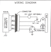
The ACU uses pulse-width modulation of the field current. This is also crude, but accepted as effective because it doesn't generate the heat that a transistorized resistance circuit would make inside the ACU. Regulating the field current using variable resistance will generate heat, see? Smooth, but hard on stuff. Really old regulators (like, much older than me, and that's old) used a stack of carbon discs that were compressed together by a spring, and the compression was relieved by a solenoid that forced the spring back. When voltage fell, the spring was able to compress the discs, lowering the stack's resistance and increasing field current, If voltage rose too much, the solenoid removed some of the spring force, relaxing the pressure on the discs. Smooth, but big and heavy and dirty and subject to heat and vibration damage. Too crude.
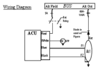
The electronic circuitry in that ACU needs only microamps from the alternator's output or the bus to change the field current. Really, really sensitive, and therein lies a problem. Any disturbance to the aircraft's electrical system can fool that ACU into thinking the voltage has risen, and the overvolt function within it will shut the alternator off. And what can disturb the airplane's system to that degree? A leaking COM antenna cable connector. RF (radio-frequency) radiation gets out and cuts through wiring and generates sharp little voltage spikes in it. The ACU mistakes this for an overvolt condition. The old electromechanical regulators were immune to this. Those sharp little spikes generated far too little current in the sensor circuit to cause trouble.
We had that problem in a late-model 185. The alternator kept going offline, but only when flying, it seemed. Couldn't find anything wrong anywhere, but I finally (finally) read the service manual, and buried in a little paragraph there was the stuff about corroded antenna cable connectors. I found it in the ceiling of the airplane. People in the airplane breathe, and in that breath is moisture. That air finds its way past the headliner and condenses on the inside of the top skins in cooler weather, and gets the antenna cable bayonet connectors wet, starting corrosion that interferes with the grounding of the cable shield. RF gets out and causes the mayhem described. I took the airplane out, started it up, hit the PTT, and bang! there was the overvolt light. At our uncontrolled field we made a radio call on takeoff, but didn't notice the light until farther along. The other end of that cable under the panel, or any splice along the way, also needs checking, as it can also get dirty/loose, corroded. I cleaned that antenna connection and the problem went away.


