EdFred
Taxi to Parking
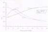
See picture for 1000's of words.
This is at cruise.
Cylinders #1-#5 were all put in brand new in April/May.
ECI Titan Nickel Bore
I should be past the break in period. 25+ hours
Break-in instructions followed meticulously.
Boroscope looks "perfect."
Oil consumption is normal/stabilized.
Oil temperature is normal - on the low end of the green range.
Oil pressure is normal.
Cylinder #6 (OH'd, been in for a year acts normal, never gets to 380)
Cylinders #2 and #4 act like #1 and #3 respectively but at a cooler temp. I've never seen #4 get above 400. #4 Usually stays well below 380. #2 is about 25 degrees cooler than #1.
The graph slides left/right a little with altitude changes.
No roughness to engine until I lean past peak.
EGT's act in relation to CHTs as the books say they should.

What say you?
This is at cruise.
Cylinders #1-#5 were all put in brand new in April/May.
ECI Titan Nickel Bore
I should be past the break in period. 25+ hours
Break-in instructions followed meticulously.
Boroscope looks "perfect."
Oil consumption is normal/stabilized.
Oil temperature is normal - on the low end of the green range.
Oil pressure is normal.
Cylinder #6 (OH'd, been in for a year acts normal, never gets to 380)
Cylinders #2 and #4 act like #1 and #3 respectively but at a cooler temp. I've never seen #4 get above 400. #4 Usually stays well below 380. #2 is about 25 degrees cooler than #1.
The graph slides left/right a little with altitude changes.
No roughness to engine until I lean past peak.
EGT's act in relation to CHTs as the books say they should.
What say you?