This is going to work,
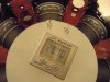
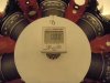
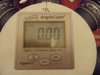
I built a disk, and a adapter for the angle cube from E-Bay, and placed the disk on the crank, and the pointer on the front of the case, then added the angle cube in the front of the crank.
found the true TDC by the piston finder method, marked that position on the disk, and set the angle cube at 0.00, now I know exactly where the crank is at all times.
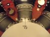
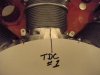
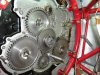
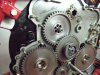
Next step is to turn the cam to the position where both valves on #1 are closed ad the exhaust valve on #7 and the intake valve on #2 are at their mid way position.
Then set the valve clearance on #1 to .027, after that I rotate the crank backwards 90 degrees and bring it up to 10 degrees BTDC,
Then advance the cam ring to start opening the #1 intake valve and install the cam drive gear, we be done with cam timing and then the accessory drive section can be assembled and mag timing can be completed.
")