Mandatory display

Let'sgoflying!

Touchdown! Greaser!
Joined
Feb 23, 2005
Messages
20,325
Location
west Texas
Display Name

Display name:
Dave Taylor
I know this is a repeat question but it came up again and I need to check again.

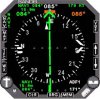
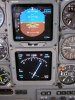
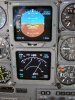
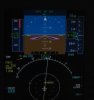
When using a gps for an approach in actual, is it not true that you must have a cdi displayed during the approach?
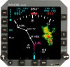
Ie for the crt displays which permit one to select moving map or cdi, you must use the cdi, and a map only display is inadequate?

References appreciated on any answer.
 
Everything I read in AIM 1-1-19 references a CDI display. Nothing "mandatory"
But I'm not done researching yet.
 
When you say moving map or CDI are you referring to an external display unit or an EHSI/EFIS type system?

If you're referring to an external display unit (ie. GNS530, etc), you can have whatever you'd like on the external box as long as you have a lateral deviation display within the pilot's field of vision.

Advisory Circular 20-138B Chapter 8-3(g)(2):
A non-numeric lateral deviation display (for example, CDI, EHSI), with a TO/FROM indication and a failure annunciation, used as primary flight instruments for aircraft navigation, for maneuver anticipation, and for failure/status/integrity indication, should have the following attributes:

(a) The displays must be visible to the pilot and located in the primary field of view.

...

(f) As an alternate means, a navigation map display must provide equivalent functionality to a lateral deviation display with appropriate map scales (scaling may be set manually by the pilot). To be approved as an alternative means, the navigation map display must be shown to meet the TSE requirements and be located in the primary field of view.
Chapter 11-8 (b)(1):
Note 1: CDI displays contained in the Control Display Unit (CDU) will most likely not be acceptable for IFR operations.
 
Last edited:
The latter. I still refer to them as cathode ray tubes, which they might not really be anymore.

See Advisory Circular 20-138B Chapter 8-3(g)(2)(f) quoted above. If it meets TFE requirements and is located in the pilot's primary field of vision, then it can be used instead of the traditional CDI display.
 
wow, thanks.

I am reading on AC20-138 that a cdi is not necessary, a map is adequate. In certain circumstances.
(I have the option of a cdi in front of me and a map in the center stack so that is what I use for approaches.)
 
wow, thanks.

I am reading on AC20-138 that a cdi is not necessary, a map is adequate. In certain circumstances.
(I have the option of a cdi in front of me and a map in the center stack so that is what I use for approaches.)

Correct. It's sort of buried in there, but it's there. B)
 
This should be addressed for your specific installation in the AFM Supplement for your GPS.
 
wow, thanks.

I am reading on AC20-138 that a cdi is not necessary, a map is adequate. In certain circumstances.
(I have the option of a cdi in front of me and a map in the center stack so that is what I use for approaches.)

What type of GPS do you have and what GPS TSO is it certified under? AC 20-138a was used to install most recent GPS units. AC 20-138b is expanded and may or may not apply to your situation, depending on what section you are referencing.

Your AFMS may deal with the subject as well. As a note, the GNS530W AFMS is not clear on the subject.
 
This should be addressed for your specific installation in the AFM Supplement for your GPS.

Since Dave's question was aimed at displaying a CDI vs. map display on a digital EFIS type system, wouldn't it be covered by an AFM supplement for the EHSI/EFIS unit? The GPS only sends the EFIS or EHSI the information.
 
For example:

Nav / CDI display

attachment.php


Map display

attachment.php


Dave, feel free to let me know if I misinterpreted your question, but I think this is what it was aimed at.
 

Attachments

  • sandel1.jpg
    sandel1.jpg
    133.2 KB · Views: 150
  • sandel2.jpg
    sandel2.jpg
    127 KB · Views: 151
The manual for the unit (GNSxls) does not specify what has to be displayed. In one section it talks about verifying the cdi is functioning properly during an approach which might hint that it is needed but I could find nothing in it stating, "map mode must not be selected for approaches" or the converse "cdi must be displayed...".
In the Supplements attached to the A/C Flight Manual (appended), on the first page it says the cdi must be displayed for manual approaches (does that mean hand-flown, and possibly heading-bug flown?). BUT on the superceding page, that line disappears.
I have attached photos of the display in map and cdi modes, however a/c is on the ground and an approach is not selected.
 

Attachments

  • s23-6.jpg
    s23-6.jpg
    650.9 KB · Views: 6
  • s23-6.1.jpg
    s23-6.1.jpg
    620.5 KB · Views: 8
  • cdi.jpg
    cdi.jpg
    672.7 KB · Views: 22
  • map.jpg
    map.jpg
    669 KB · Views: 22
The manual for the unit (GNSxls) does not specify what has to be displayed. In one section it talks about verifying the cdi is functioning properly during an approach which might hint that it is needed but I could find nothing in it stating, "map mode must not be selected for approaches" or the converse "cdi must be displayed...".
In the Supplements attached to the A/C Flight Manual (appended), on the first page it says the cdi must be displayed for manual approaches (does that mean hand-flown, and possibly heading-bug flown?). BUT on the superceding page, that line disappears.
I have attached photos of the display in map and cdi modes, however a/c is on the ground and an approach is not selected.

Your question is very equipment specific so it's difficult to place an answer that accurately describes every system out there. Looking at the manual and pictures you posted, in map mode there is a digital readout of desired track lateral deviation at the bottom (0.00R).

Since the manual requires the approach to be accomplished with the flight director, I would assume "manual approach" to mean hand flown (not coupled to the autopilot).
 
Good discussion.

Not sure what is "legal" but legal has never equalled smart. I've been told and strongly believe you should never fly the plane using the magenta line (ie. using the moving map) for course guidance. Depending on the display scale you could be over a 1/2 mile off course and still "appear" to be on the magenta line. Personally, I wouldn't dream of using the moving map page to shoot an approach, situational awareness during cruise of course, but once I hit the IAF my instrument scan is locked to the primary instruments to include whatever form of HSI is in the plane. A CDI "display" whether it is a stand alone instrument or preferably part of an HSI is mandatory in my book. Secondly, for the more typical GA GNS430/530 GPS installation using the CDI "display" on the bottom of the GPS screen would be a no go in my book as well. The GPS is typically not directly in your scan; turning your head back and forth during a real IMC approach is very dangerous.
 
Good discussion.

Not sure what is "legal" but legal has never equalled smart.

That's why I like the Proline 21 setup which allows you to be in map mode but still retain a CDI just below the attitude indicator portion of the PFD.

attachment.php
 

Attachments

  • proline_21_pfd.jpg
    proline_21_pfd.jpg
    147.3 KB · Views: 107
Good discussion.

Not sure what is "legal" but legal has never equalled smart. I've been told and strongly believe you should never fly the plane using the magenta line (ie. using the moving map) for course guidance. Depending on the display scale you could be over a 1/2 mile off course and still "appear" to be on the magenta line. Personally, I wouldn't dream of using the moving map page to shoot an approach, situational awareness during cruise of course, but once I hit the IAF my instrument scan is locked to the primary instruments to include whatever form of HSI is in the plane. A CDI "display" whether it is a stand alone instrument or preferably part of an HSI is mandatory in my book. Secondly, for the more typical GA GNS430/530 GPS installation using the CDI "display" on the bottom of the GPS screen would be a no go in my book as well. The GPS is typically not directly in your scan; turning your head back and forth during a real IMC approach is very dangerous.

I think everyone has to find out for themselves what they're most comfortable with. I typically use both the external CDI and the moving map when flying an approach. Looking to the right to see the GPS doesn't bother me.

BTW, I thought it was was required for the moving map to automatically set the scale when a GPS approach has been activated.

A big advantage of including the moving map in my scan is one that I discovered accidentally. If one inadvertently hits the OBS button in turbulence, the fact that there is a white line instead of a magenta one ahead is the most obvious clue that something has gone wrong. I like to practice GPS approaches in VMC even when I can't log them (due to not having a safety pilot), and the significance of this issue became ubundantly clear when I had a face full of mountain after crossing a fix that was supposed to include a turn to a new heading.
 
BTW, I thought it was was required for the moving map to automatically set the scale when a GPS approach has been activated.
That is not true. In fact you don't need to have a moving map displayed or even installed to do a GPS approach.
 
I know the map doesn't have to be displayed, but I thought I had seen the GNS-430 automatically changing its map scale on approaches. I suppose it may just be something that Garmin decided to do on their own, or maybe I'm mis-remembering it. I'll have to check next time I fly an approach.
 
If one inadvertently hits the OBS button in turbulence, the fact that there is a white line instead of a magenta one ahead is the most obvious clue that something has gone wrong.

Actually on the GNS430, pressing the OBS button will only inhibit waypoint sequencing and will still display a magenta line with the desired course (usually set by the #1 nav or HSI) to the waypoint. Beyond the waypoint, the line will continue but is white in color to denote that it is on the "FROM" side of the waypoint.

gns430_2_1.jpg


I know the map doesn't have to be displayed, but I thought I had seen the GNS-430 automatically changing its map scale on approaches. I suppose it may just be something that Garmin decided to do on their own, or maybe I'm mis-remembering it. I'll have to check next time I fly an approach.

It's called the auto-zoom function and can be turned on or off by user preference by pressing the "MENU" button on the second NAV page and selecting "AUTO ZOOM" to "OFF."
 
Actually on the GNS430, pressing the OBS button will only inhibit waypoint sequencing and will still display a magenta line with the desired course (usually set by the #1 nav or HSI) to the waypoint. Beyond the waypoint, the line will continue but is white in color to denote that it is on the "FROM" side of the waypoint.

gns430_2_1.jpg

Yes, that's what I'm referring to. The fact that waypoint sequencing is inhibited in OBS mode means that the line on the "from" side of the fix will stay white after the airplane has crossed the fix, instead of turning magenta. Thus, as soon as the fix is crossed, the moving map makes it obvious if the unit has been put in OBS mode accidentally.

I presume it would also make it obvious if the waypoints failed to auto-sequence for some other reason.

In general, my conclusion is that if I find myself navigating along a white line instead of a magenta one, something's probably wrong.

It's called the auto-zoom function and can be turned on or off by user preference by pressing the "MENU" button on the second NAV page and selecting "AUTO ZOOM" to "OFF."

OK, that explains what I'm seeing.
 
I like to practice GPS approaches in VMC even when I can't log them (due to not having a safety pilot), and the significance of this issue became ubundantly clear when I had a face full of mountain after crossing a fix that was supposed to include a turn to a new heading.

Do you remember the approach that you are talking about?
 
Do you remember the approach that you are talking about?

PAO GPS Rwy 31:

http://download.aopa.org/ustprocs/current/SW-2/pao_gps_rwy_31.pdf

ATC always assigns direct DOCAL, and my bearing inbound to that fix was probably in the vicinity of 300 or 310. The CDI did not switch to the 329 bearing needed when I passed DOCAL, and I later figured out that this happened because I had accidentally bumped the OBS button in turbulence.

Of course, the flag on the external CDI would have switched to "from" on crossing the fix, and the green OBS annunciation would have been lighted above the button, and either of those would indicate that there was a problem, but I feel that the lack of a magenta line ahead is a more obvious warning, and I like problem warnings to be as obvious as possible.
 
At the end of the day, it's a flight manual supplement question since only the flight manual supplement(s) for the installed equipment address the integrated system as installed.
 
At the end of the day, it's a flight manual supplement question since only the flight manual supplement(s) for the installed equipment address the integrated system as installed.

I would think so as well, but reading thru the GNS530W AFMS it discusses the requirement for an external CDI with VLOC as the source for a VOR or an ILS approach, but is silent on any requirement for a GPS approach.
 
Thanks for the info and guidance.
I was figuring on a blanket rule that applied to all devices, all a/c; "thou must always have the cdi displayed to fly a gps approach; moving map only is unacceptable".
I gather from the comments that it is device-specific. I wish the one I mentioned had a manual that was more explicit.
 
Which AFMS -- the one in your plane? The generic version which must be individualized for each installation?

Yes to the first part, it is the one in the aircraft. The pre-W versions had a sample that you had to customize and obtain FAA approval thru a field approval, but this was done away with for the W version. The W versions are already FAA approved (with signature) under the STC and AML and only require blanks to be filed in and check marks to be made to reflect configuration. See the attached AFMS.

View attachment GNS500W AFMS SW Ver 3 30 Rev B.pdf
 
At the end of the day, it's a flight manual supplement question since only the flight manual supplement(s) for the installed equipment address the integrated system as installed.


The flight manual will tell you how to use the equipment.

the requirement is in the TSO For the equipment, this one is TSO-C129a, AIRBORNE SUPPLEMENTAL NAVIGATION EQUIPMENT USING THE GLOBAL POSITIONING SYSTEM

it starts
(iii) Class C( ). Equipment consisting of a GPS sensor that provides data to an integrated navigation system (i.e., flight management system, multi-sensor navigation system, etc.) which provides enhanced guidance to an autopilot or flight director in order to reduce flight technical error. Class C equipment is limited to installations in aircraft approved under 14 CFR Part 121 or equivalent criteria. (It is intended that this class of equipment need not meet the display requirements applicable to the other equipment classes of this TSO.) The equipment consisting of a GPS sensor must meet all of the Class C( ) requirements specified in this TSO in order to be identified with a Class C( ) marking.
 
Yes to the first part, it is the one in the aircraft.
Then that only applies to the equipment suite in your airplane. How it would read when integrated with a different set of equipment and different equipment locations in the plane might be very different.
 
Then that only applies to the equipment suite in your airplane. How it would read when integrated with a different set of equipment and different equipment locations in the plane might be very different.

It reads the same. The only differences are the aircraft unique ID, make, model, and the boxes that are checked. It applies to all aircraft on the AML and that interface to the equipment or interfaces specifically approved in the installation manual as specified by the STC and installed in compliance with the install manual.

Out of 100 installs, one might not find the basis in the STC or AML to interface to a piece of equipment in one or two cases, in which case they would seek additional approval authority thru a field approval. If the equipment required a difference in the AFMS, then they could use the approved document as a sample. The vast majority of installs use the canned FAA approved AFMS.

This method of developing the approved AFMS via STC with AML was pioneered by Apollo and makes installation much easier and less time consuming. It is used on the GNS430W/530W, G500/G600, Aspen, and others.

Prior to the FAA pre approved AFMS, one needed to make the appropriate changes to match the installation. This was true for the GNS430/530 and was a PIA for the installer. Some new equipment, such as ADSB units will have to be individualized for the time being. Also, some equipment manufacturers are unable to do the AML thing and just get a STC for single installation along with a sample AFMS and put the approval thru the field approval process.
 
The flight manual will tell you how to use the equipment.

the requirement is in the TSO For the equipment, this one is TSO-C129a, AIRBORNE SUPPLEMENTAL NAVIGATION EQUIPMENT USING THE GLOBAL POSITIONING SYSTEM

it starts
(iii) Class C( ). Equipment consisting of a GPS sensor that provides data to an integrated navigation system (i.e., flight management system, multi-sensor navigation system, etc.) which provides enhanced guidance to an autopilot or flight director in order to reduce flight technical error. Class C equipment is limited to installations in aircraft approved under 14 CFR Part 121 or equivalent criteria. (It is intended that this class of equipment need not meet the display requirements applicable to the other equipment classes of this TSO.) The equipment consisting of a GPS sensor must meet all of the Class C( ) requirements specified in this TSO in order to be identified with a Class C( ) marking.

Tom,

The TSO describes three main classes of equipment with several subclasses. Class A is a GPS/Navigator such as a Garmin 430. Class B and C are black boxes such as the GIA63 in a G1000 system and the GPS box itself doesn't have a display, but rather a FMS or FMS like system provides display functions. Often other navigation sources are integrated into the FMS, such as DME-DME or INS or VOR/Localizer and the specific navigation equipment doesn't have its own display. This is what the TSO is describing, not the display requirements of the CDI that is described under its own TSO and is attached to the system.
 
Back
Top