JPI MAP connector mystery solved.

Chip Sylverne

Final Approach
Joined
Jun 17, 2006
Messages
5,893
Display Name

Display name:
Quit with the negative waves, man.
The connector used at the JPI map sensor, for those who prefer to make their own harness, is a Molex 2695 4 pin p/n 0010112044, with gold crimp sockets 0008550129.
Mouser has it for .25 the sockets are .64 each.

A perfectly acceptable 14lb crimp can be made with a JST hand crimper.
 
Chip!

Your information re the JPI MAP connector was exactly what I was looking for. But, I'm also searching for the pinout.

JPI references their harness wire color - but if you roll your own...

Any chance you can describe the pinout?

Thanks a million!

Peter
 
If you mean the rgb on the sensor itself, I can't recall, but call Shelby at JPI support. He is very helpful and if he doesn't know he'll find someone who does.
 
Guess I'll make that call. Installed an 830 over the last couple of weeks, this MAP sensor is the final piece.

Thanks!
 
So...

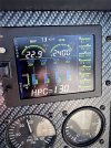
My JPI EDM 830 (new install during a panel refresh) is now fully operational. Big thanks to Chip for posting the molex MAP connector. That connector works, but I think is not the actual correct part; as arrived, it would not fit into the sensor- the "ears" on the connector are too tall, and need to be shaved down- pretty much removed - to fit into the sensor. The sensor has no provision for those "ears." Also, there's no locking mechanism to secure the connector into the sensor. The contacts are a good fit, and it's snug enough that, with a tie wrap, the connector will certainly stay in place.

The JPI documentation- especially the early stuff, is pretty bad. Anyone that's followed their printed guidance for a EDM 700 or similar device has undoubtedly encountered this. But the user guide for the 730 / 830 is good, and has some installation information that is very helpful.
 

Attachments

  • JPI EDM 830 installed.jpg
    JPI EDM 830 installed.jpg
    169.1 KB · Views: 4
Back
Top