bob_albertson
Pre-takeoff checklist
Now that I have found where all the cool guys hang out, I am so happy and unbored (is that a word  ).
).
Anyways, I'm reading all that I can on these types of engines. A lot of what the AFH has to say is Greek to me without some explanation of what the other things do.... I like to have a complete picture of the system.
So, Fixed shaft (direct drive) vs. Split Shaft (free turbine): On a fixed shaft engine they say the engine is made of a combustion chamber (I understand that one, gee who wouldn't ), transition liner, and turbo plenum. That is all they say about the last two parts of the engine.... They don't even have a good diagram about a transition liner and turbo plenum. Google isn't getting much in the way of descriptions for me. The way most things seem, those two must have a more used slang term??
If an engine failure occurs, they say that the compressor creates a huge amount of drag, and as a secondary aid to prevent being stuck with the prop in the low pitch position... some manufacturers incorporate a NTS system (Negative Torque Sensing). I'm looking for a little clarification on what they said.... Is it just ram air flow through the engine that keeps the compressor spinning during an engine failure? If the propeller is windmilling, it is because of the compressor and not aerodynamic forces on the propeller blades?
For the direct drive engines, they said that power changes are made by increasing fuel flow and propeller blade angle rather than engine speed.... But, isn't it fuel flow (condition lever) that controls engine RPM? I was a little cornfused because of the relationship of fuel flow and RPM since the fuel affects the engine speed (RPM)?
The split shaft engines.... they have a centrifugal compressor... So does that just mean that N2 is a measure of the air pressure at the gas producer (turbine?) against the chamber walls? Does that engine also incorporate a transition liner?
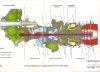
I can follow the air's progress through each compressor, but the book doesn't do a good job of explaining the reason why the compressed air reverses direction twice. I am assuming it is caused by the turbine that drives the compressor, sending the air towards the second turbine that drives the prop, and that compressor sending it back to the other one more time before the air makes it out to the exhaust.
Which engine produces more exhaust thrust?
 ..... and that happened
Bob
).Anyways, I'm reading all that I can on these types of engines. A lot of what the AFH has to say is Greek to me without some explanation of what the other things do.... I like to have a complete picture of the system.
So, Fixed shaft (direct drive) vs. Split Shaft (free turbine): On a fixed shaft engine they say the engine is made of a combustion chamber (I understand that one, gee who wouldn't
), transition liner, and turbo plenum. That is all they say about the last two parts of the engine.... They don't even have a good diagram about a transition liner and turbo plenum. Google isn't getting much in the way of descriptions for me. The way most things seem, those two must have a more used slang term??If an engine failure occurs, they say that the compressor creates a huge amount of drag, and as a secondary aid to prevent being stuck with the prop in the low pitch position... some manufacturers incorporate a NTS system (Negative Torque Sensing). I'm looking for a little clarification on what they said.... Is it just ram air flow through the engine that keeps the compressor spinning during an engine failure? If the propeller is windmilling, it is because of the compressor and not aerodynamic forces on the propeller blades?
For the direct drive engines, they said that power changes are made by increasing fuel flow and propeller blade angle rather than engine speed.... But, isn't it fuel flow (condition lever) that controls engine RPM? I was a little cornfused
because of the relationship of fuel flow and RPM since the fuel affects the engine speed (RPM)? The split shaft engines.... they have a centrifugal compressor... So does that just mean that N2 is a measure of the air pressure at the gas producer (turbine?) against the chamber walls? Does that engine also incorporate a transition liner?
I can follow the air's progress through each compressor, but the book doesn't do a good job of explaining the reason why the compressed air reverses direction twice. I am assuming it is caused by the turbine that drives the compressor, sending the air towards the second turbine that drives the prop, and that compressor sending it back to the other one more time before the air makes it out to the exhaust.
Which engine produces more exhaust thrust?
..... and that happened Bob