Alternator Stator Port- Low Voltage Light Came One

Alex Morris

Filing Flight Plan
Joined
Mar 17, 2019
Messages
8
Location
Eunice, La
Display Name

Display name:
Froggy
So here's how I missed a flying lesson on a perfect day to fly and then was nearly kicked out of a machine shop due to a low voltage light. Cranked up my Cessna 172M. The Alternator is a Ford. I believe it's as old as the early 90s. In around 2006 these were changed per my logbook: the overvoltage sensor, starter contactor, battery contactor, overvoltage capacitor, filter, master switch, & voltage regulator. SO.. yesterday instead of flying, I removed the alternator and brought it a local auto/machine shop simply to have it tested. It tested 'working but your stator port isn't putting out any voltage' to which the guy (who has pretty extensive experience) points to a terminal on the alternator... When I dismantled the alternator, NOTHING was connected to this port with a 'STA' stamp on the alternator. I returned later after bringing him my voltage regulator. He took a quick look and said 'yep, it's got a prong for the stator, you need to have your stator port on the alternator connected.' I made yet another mention that nothing was connected to that port on the alternator. His next words were "I've been doing this sh*t for 50 years and if you don't believe me then you'll just have to take this somewhere else." Well after settling the old man down, he did persist to ensure that something must be connected to that STA port.
Anyway, since 1973, this plane seemed to have operated without the STA port on the Ford 'tractor alternator' so something is different. Could my voltage regulator be out again? I'm about 99% sure it's the old style (not the solid state one that Zeftronics makes). Does anyone have experience with a simple swap from the old "analog" ACU to the Zeftronics? PS, he never did attempt to test the ACU "voltage regulator" with my alternator. Also as far as I could tell, all connections/terminals on the Alt/batt/ACU were good and clean. Also, PS while the low voltage light was on after cranking, we did confirm on the ammeter that there was a draw on the battery instead of a small charge during normal op. Thanks in advance.
 
Get an experienced mechanic to troubleshoot and repair and certify. Pay him generously and promptly. Repeat as required. :)
 
The stator terminal is NOT used on those alternators in a 172 or any other Cessna. The regulator's "S" terminal is connected to the alternator side of the master switch, and turning that switch on turns the regulator on. In a car, that S terminal on the alternator was connected to the delta junction of the alternator stator Inside the alternator and to the regulator's S terminal so that when the alternator started spinning it generated a small current to turn the regulator on. That's what is fooling your local auto/machine shop guy. In the airplane we need the ability to turn a renegade alternator off in flight to avoid a fire or whatever.

Failed charging systems are most commonly due to worn-out alternator brushes. The airplane's alternator spins faster than the one in a car, so those brushes wear out faster. Aside from that, you might have a failed diode in it, or the regulator is failed, or one of the breakers (ALT output 60 amp or the misnamed Field breaker 5 amp, which feeds the ALT side of the master switch). There are plenty of places for a bad connection to cause trouble, too.
 
upload_2019-3-20_21-7-19.png

OK. Look at the diagram from the 172M POH. Note that the Alternator's S terminal isn't even shown, because it's not used. The regulator's S terminal goes to the ALT switch at the Master. Show that diagram to your machine shop guy.
 
The STA terminal on an alternator seems to be unique to Ford. It is connected to the common of the three armature windings which are arranged in a wye configuration. It makes for a convenient way to check the rectifier diodes without disassembly. The only time I have seen it connected to anything external is to an electric choke as in my wife's Mustang. This allows the choke to heat up and pull off only when the engine is running.

The S terminal on your regulator is connected to a switched battery source, i.e. the ignition switch in a car or the master switch in an airplane. This allows the battery to energize the field via the regulator. Unlike a DC generator, a typical alternator cannot "start" itself due to the voltage drop of the rectifier diodes and hence needs the battery to supply the field current.

I suggest you turn the master switch on and then check for voltage at terminal S on the regulator, terminal F on the regulator, and terminal F on the alternator. If it is missing at any of these points the location of the fault should be apparent.
 
Last edited:
The STA terminal on an alternator seems to be unique to Ford. It is connected to the common of the three armature windings which are arranged in a wye configuration. It makes for a convenient way to check the rectifier diodes without disassembly. The only time I have seen it connected to anything external is to an electric choke as in my wife's Mustang. This allows the choke to heat up and pull off only when the engine is running.

The S terminal on your regulator is connected to a switched battery source, i.e. the ignition switch in a car or the master switch in an airplane. This allows the battery to energize the field via the regulator. Unlike a DC generator, a typical alternator cannot "start" itself due to the voltage drop of the rectifier diodes and hence needs the battery to supply the field current.

I suggest you turn the master switch on and then check for voltage at terminal S on the regulator, terminal F on the regulator, and terminal F on the alternator. If it is missing at any of these points the location of the fault should be apparent.

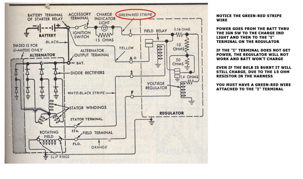
Agree with all of that, mostly. The stator is indeed a wye configuration instead of a delta. It was late last night when I wrote that and got it wrong. And newer installations do fire the S terminal on the regualtor from the ignition switch. However, the vintage of the Ford installation in a typical Cessna comes from the mid-1960s, when Ford did it this way:

1hmpK.jpg


Note the regulator's S terminal's connection to the alternator's stator terminal. The field current was initially fed from the charge light circuit, enough to get the stator pushing a bit of current to fire the regulator. That doesn't apply to the Cessna installation, even though the overvolt/undervolt light is connected the same way, without the bypass resistor. The Cessna system will run just fine with a burnt-out bulb. The ALT switch closes the field relay, connecting the A terminal to the regulator's field supply circuitry. That A terminal is the one that goes to the aircraft bus and is live when the master is on.
 
Good information, shows the old guy in the machine shop was right about the STA-to-S connection at least in the case of old Fords. However, this does not apply to the OP. He should continue to troubleshoot the regulator and/or associated wiring as the alternator has been ruled OK.
 
Another thought: IIRC, the voltage on the STA terminal on our Mustang was only 7 volts, or 1/2 output voltage. If this is true, it may be that Cessna was applying 14V to a 7V design field relay coil. Egads! This would account for the short regulator lifetime the OP has experienced, and likely the current condition i.e. if the field relay winding was burned out (open) there would be no charging. Is it possible Cessna did something this stupid?

OP, suggest you measure the resistance of the regulator S terminal to ground. I'm guessing it should be <50 ohms. If much greater or open, you've found the problem.

Cessna used an ordinary 12-volt regulator, and the field relay was fine. In fact, those old electromechanical regulators lasted a very long time, and I had far more trouble with the electronic replacements once the mechanical units weren't available any more. Switching off the alternator when the engine is running creates a voltage spike from the alternator's field windings, and that spike goes right into the regulator via its F terminal. Electronic devices will fry much more quickly than those old mechanical units.
 
Back
Top