Tom-D
Taxi to Parking
- Joined
- Feb 23, 2005
- Messages
- 34,740
- Display Name
Display name:
Tom-D
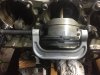
Yesterday I went to help a 170-B owner replace two cylinders on his 0-300. The engine has been running fine, good oil pressure, good power, smooth operation all around. Recently started to exhibit a little morning sickness, #2 & #5 show a drop in compression since last annual. These cylinders are Superior Millennium with about 900 Hours since new. The Owner wanted them pulled to see what could be done to restore the engine to good health.
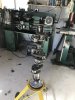
We got #2 off and found the piston pin was frozen in the piston, by heating the piston we removed the piston pin from the piston just to find the piston had started to gall metal to the pin. The decision was made simply to replace #2 with the spare new cylinder, So we move over to #5. and find the same thing happening.
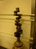
Now for the kicker, we can now see the cam and lifters behind these two cylinders, the forward cam lobe that runs the exhaust valve for #6 is near gone, and the lifter face is eroded really bad.
The rods on both #2 & #5 can be wobbled about 3-4 degrees sideways showing the rod bearing are excessively worn.
The owner made the decision to overhaul the 0-300-A. Log books show 1750 +- since last major.
you just never know what you will find when you open Pandora's box.")
We got #2 off and found the piston pin was frozen in the piston, by heating the piston we removed the piston pin from the piston just to find the piston had started to gall metal to the pin. The decision was made simply to replace #2 with the spare new cylinder, So we move over to #5. and find the same thing happening.
Now for the kicker, we can now see the cam and lifters behind these two cylinders, the forward cam lobe that runs the exhaust valve for #6 is near gone, and the lifter face is eroded really bad.
The rods on both #2 & #5 can be wobbled about 3-4 degrees sideways showing the rod bearing are excessively worn.
The owner made the decision to overhaul the 0-300-A. Log books show 1750 +- since last major.
you just never know what you will find when you open Pandora's box.